Parametric Optimization of a 180° Pipe Bend
A complete simulation-driven optimization workflow combining parametric geometry generation, automated meshing, CFD simulation, and optimization within a single engineering environment.
9
Design Variables
180°
Pipe Bend
Minimize
Pressure Loss
100%
In-House Workflow
Not all geometric regions of a pipe bend contribute equally to hydraulic losses. The optimization process revealed which shape modifications have the greatest impact on overall hydraulic performance.
Every simulation, parameter set, and performance metric was automatically captured, transforming individual CFD runs into a reusable engineering knowledge base for future design exploration, surrogate modeling, and decision support.
Why This Study Matters
While the geometry itself is intentionally simple, the workflow demonstrates the same optimization process that applies to pumps, fans, propellers, turbines, biomedical devices, and other complex engineering systems. By focusing on a well-understood problem, the study highlights the optimization methodology rather than the complexity of the geometry.
Study Overview
A simple geometry. A complete optimization workflow.
Question
How do local diameter variations influence hydraulic losses in a 180° pipe bend?
This study investigates how changes in pipe diameter at nine predefined locations affect the hydraulic performance of a 180° bend. The objective is to minimize total pressure losses while maintaining a fully automated optimization workflow.
Approach
Parametric geometry generation, CFD optimization loop.
Each design candidate is automatically generated, meshed, simulated, and evaluated. Geometry creation, meshing, CFD analysis, and optimization are performed within a single engineering environment without relying on external software packages.
Finding
Not all geometric regions contribute equally to pressure losses.
The study reveals which parts of the bend have the greatest influence on hydraulic performance and demonstrates how optimization can systematically identify the most effective shape modifications.
Outcome
A reusable workflow for simulation-driven design optimization.
While the geometry itself is intentionally simple, the methodology can be directly applied to more complex engineering systems such as pumps, fans, propellers, turbines, and biomedical devices.
Engineering Challenge
Why was this study performed?
Our optimization projects often focus on complex engineering systems such as pumps, turbines, propellers, or biomedical devices. However, the underlying workflow remains the same regardless of geometric complexity.
The objective of this study was to create a simple yet meaningful optimization example that demonstrates the complete simulation-driven design process. An 180° pipe bend was selected because it contains well-understood flow phenomena while remaining easy to understand and visualize.
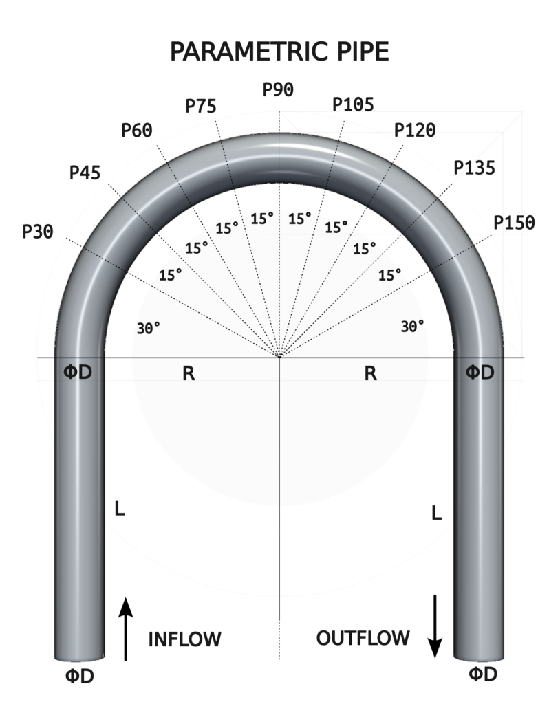
The geometry was fully parameterized. Optimization used nine independent design variables (P30 – P150) controlling the local pipe diameter at different locations along the bend. The goal was to identify shape modifications that reduce total pressure losses while demonstrating a fully automated workflow for geometry generation, meshing, CFD simulation, optimization, and data collection.
The particular pipe has the following dimensions: L = 0.3 m, R = 0.2 m, D = 0.1 m.
Simulation Workflow
From design variables to engineering knowledge.
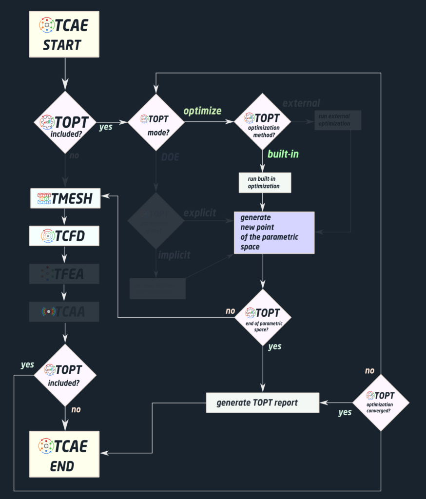
The optimization process is structured as an automated loop that connects geometry generation, meshing, CFD simulation, and design optimization.
Starting from a set of design variables, a new geometry is automatically created and passed to the meshing stage. The generated mesh is then evaluated using CFD simulations, where hydraulic performance is assessed based on total pressure losses across the pipe bend.
The Direct Optimization algorithm analyzes the results, identifies promising design candidates, and proposes new parameter combinations for evaluation. This process continues until the specified stopping criteria are reached.
Because every step is automated, hundreds of design variants can be evaluated without manual intervention. At the same time, all simulation parameters, performance metrics, and results are systematically stored, creating a reusable foundation for future design exploration, surrogate modeling, and engineering knowledge extraction.
Automation replaces repetitive work, allowing engineers to focus on design decisions rather than simulation execution.
CFD Simulation Setup
Geometry Builder
180° Pipe Bend
The study uses a simple Python script to create the geometry of the pipe using nine design variables that control the local diameter at selected locations along the bend, enabling smooth shape evolution during optimization. The script reads the nine input values (parameters P30 – P150) and returns the corresponding STL geometry files: inlet.stl, outlet.stl, and wall.stl. The solid.stl file for FEA is optional.
Mesh
Automated Mesh Generation
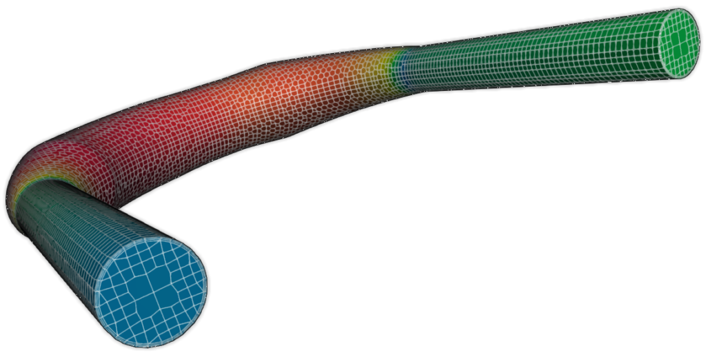
Each design candidate is automatically meshed using the integrated meshing tool – snappyHexMesh. The meshing process is fully automated to ensure consistency and repeatability throughout the optimization study. The mesh is hex-dominant (80%) with three cells in the inflation layer. The number of cells is relatively low (100-200k) to keep each simulation time as low as possible.
Physics
Steady-state Turbulent Flow
The simulation models incompressible turbulent flow through the pipe bend. The objective is to evaluate hydraulic losses generated by the geometry and quantify their impact on overall performance.
The working fluid is water, modeled as an incompressible Newtonian fluid with constant density and viscosity at 20 deg C. The flow conditions correspond to fully turbulent internal flow within the pipe bend.
Turbulence is modeled using the k-ω SST model, which combines the robustness of the k-ω formulation near walls with the free-stream behavior of the k-ε model. The model is widely used for engineering applications involving adverse pressure gradients and flow separation.
The simulations are performed using a finite-volume, steady-state incompressible RANS solver. Pressure-velocity coupling is handled iteratively until convergence criteria are satisfied and hydraulic performance metrics stabilize.
- Simulation type: Stator
- Time management: steady-state
- Physical model: Incompressible
- Number of components: 1 [-]
- Wall roughness: none
- Physical model: Incompressible
- Outlet: Static pressure 0 [m2/s2]
- Turbulence: RANS
- Turbulence model: k-omega SST
- Wall treatment: Wall functions
- Turbulence intensity: 5%
- Speedlines: 1 [-]
- Simulation points: 1 [-]
- Fluid: Water
- Reference pressure: 1 [atm]
- Dynamic viscosity: 1.0 × 10E-6 [Pa⋅s]
- Ref density: 996 [kg/m3]
- CFD CPU Time: 0.1 core.hours/point
Boundary Conditions
Fixed Flow Rate
The pipe operates at a prescribed flow rate of 250 l/s at the inlet and zero static pressure at the outlet, and otherwise standard BCs for all other quantities. Total pressure losses across the bend are evaluated for each design candidate and used as the primary performance metric.
- Inlet: volumetric flow rate 250 [l/s]
- Outlet: Static pressure 0 [m2/s2]
- Mesh motion: Static
Optimization Setup
The objective of the optimization process is to identify pipe geometries that minimize hydraulic losses while respecting the predefined design space. The study uses Direct Optimization implemented directly within TCAE, enabling fully automated design exploration without relying on external optimization software.
Distribution of Parameters
Design Space
Nine independent design variables control the local pipe diameter at selected locations along the bend. This parameterization provides sufficient flexibility for smooth shape evolution while keeping the design space manageable.
| Parameter | Minimum [m] | Baseline [m] | Maximum [m] |
|---|---|---|---|
| P30 | 0.04 | 0.05 | 0.15 |
| P45 | 0.04 | 0.05 | 0.15 |
| P60 | 0.04 | 0.05 | 0.15 |
| P75 | 0.04 | 0.05 | 0.15 |
| P90 | 0.04 | 0.05 | 0.15 |
| P105 | 0.04 | 0.05 | 0.15 |
| P120 | 0.04 | 0.05 | 0.15 |
| P135 | 0.04 | 0.05 | 0.15 |
| P150 | 0.04 | 0.05 | 0.15 |
Optimization Objective
The optimization objective is to minimize total pressure losses across the pipe bend. Lower pressure losses correspond directly to improved hydraulic efficiency and reduced energy consumption.
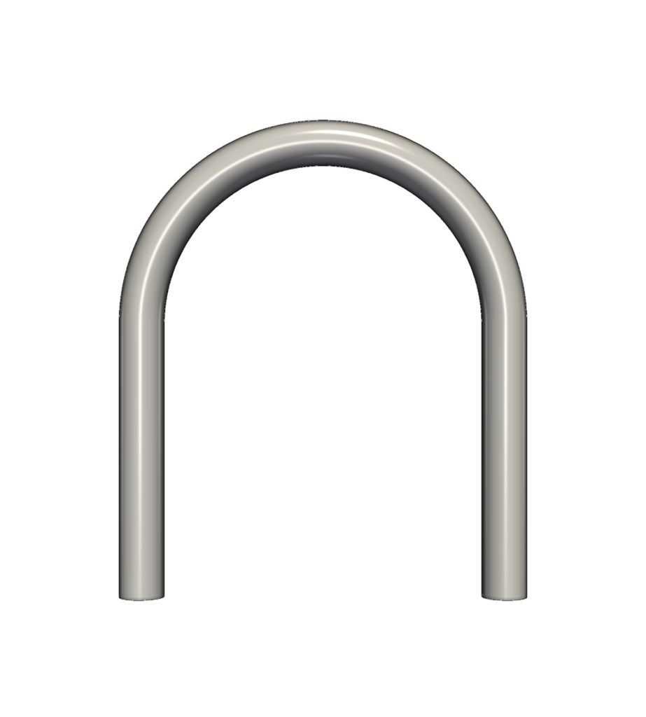
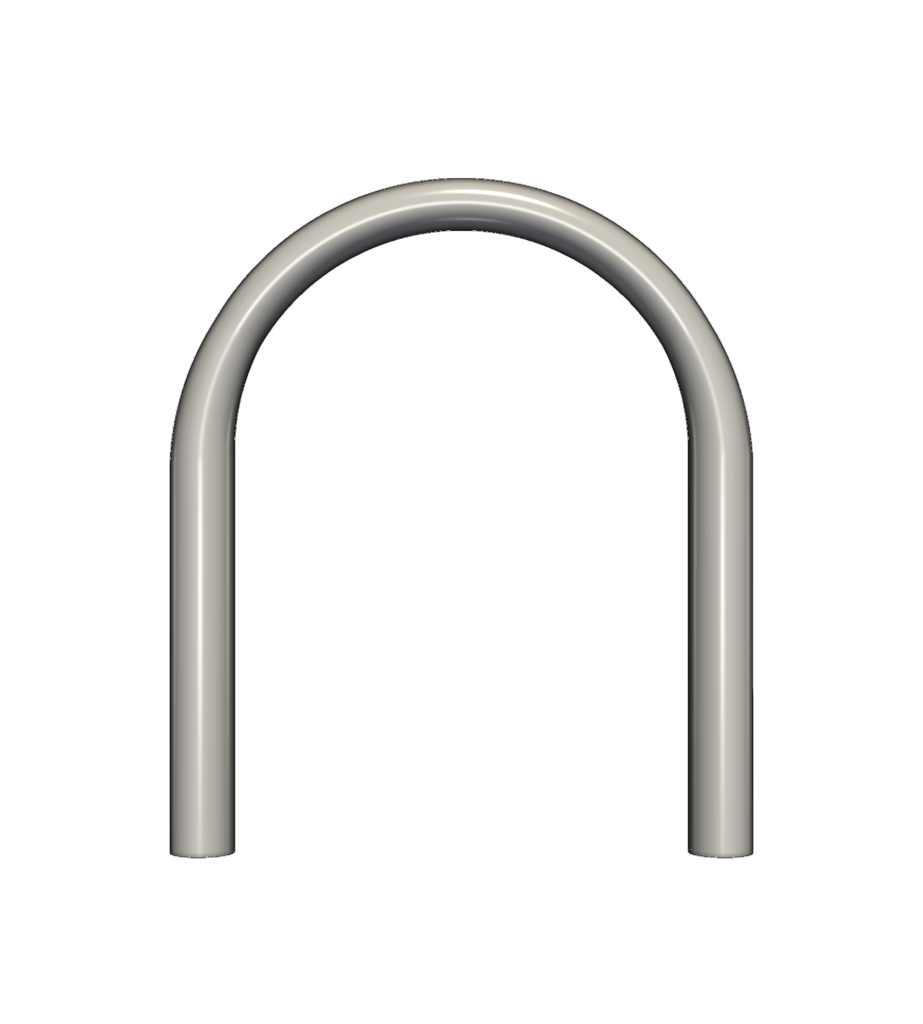
Baseline Geometry
Optimization Method
For simplicity, this case study uses the TCAE built-in Direct Optimization algorithm [1], which automatically explores the design space and identifies improved design candidates. Because the optimizer is integrated directly into the simulation workflow, no external optimization packages or custom scripting are required.
All parameters Min
Engineering Note
In general, the quality of any optimization study is determined more by the chosen parameterization than by the optimization algorithm itself. A well-designed parameteric space allows meaningful improvements and manageable computational cost.
Finally, it’s necessary to have a reliable and accurate baseline CFD model before starting optimization. A poor baseline model often leads to misleading optimization results.
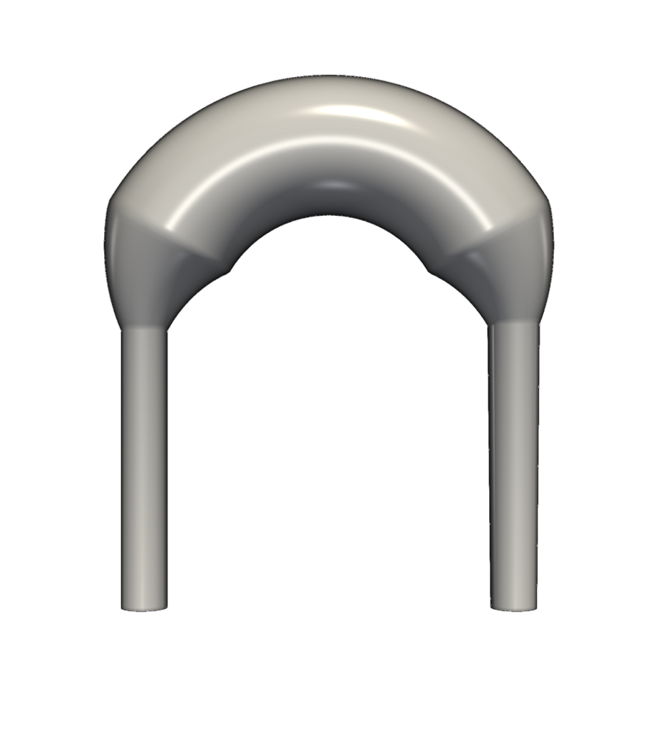
All parameters Max
Results
Geometry Evolution
The optimization process gradually modified the local pipe diameters to reduce hydraulic losses. Starting from the baseline geometry, each design iteration introduced new shape variations based on the performance of previously evaluated designs.
The maximum number of evaluations (Max Runs) was set to 100 for this study. However, optimization runs can also be controlled using relative or absolute convergence tolerances for the objective function. When the rate of improvement falls below the specified threshold, the optimization terminates automatically, avoiding unnecessary simulations and improving computational efficiency.
Pressure Field
Velocity Field
Objective Function Evolution
Baseline Design
Best Design
Worst Design
Pressure Loss Reduction
The optimization process successfully reduced hydraulic losses across the 180° pipe bend. The baseline design achieved a hydraulic efficiency of 0.802, while the optimized geometry reached 0.832.
Although the geometric modifications appear relatively modest, they resulted in a 3.7% improvement in hydraulic efficiency. The study demonstrates how systematic design exploration can identify performance gains that would be difficult to discover through manual trial-and-error design changes.
More importantly, the project validates the complete optimization workflow, from parametric geometry generation and CFD evaluation to automated design improvement and knowledge extraction.
Engineering Ensights
Optimization produces designs. Simulations produce results. Knowledge produces better decisions.
Insight 1: Parameterization Matters
A well-designed parameter space is often more important than the optimization algorithm itself.
The nine design variables provided sufficient freedom for smooth shape evolution while keeping the design space manageable. Too few variables would restrict possible improvements, while excessive design freedom would unnecessarily increase the optimization complexity.
Insight 2: Not All Variables Are Equally Important
Optimization helps identify where engineering effort matters most.
Although nine design variables were available, the optimization process revealed that only certain regions of the bend have a dominant influence on hydraulic performance. This observation is particularly valuable for future design studies, where engineering effort can be focused on the most influential parameters.
Insight 3: Small Shape Changes Can Produce Measurable Gains
Performance improvements do not always require radical redesigns.
The optimized geometry achieved a 3.7% improvement in hydraulic efficiency, increasing from 0.802 to 0.832. While the geometric modifications appear relatively modest, they significantly reduce hydraulic losses and demonstrate the value of systematic design exploration.
Insight 4: Automation Scales Better Than Manual Design Iteration
Engineers should spend time making decisions, not running simulations.
The study demonstrates how repetitive tasks such as geometry creation, meshing, simulation execution, and result evaluation can be fully automated. Once the workflow is established, engineering effort shifts from simulation execution to interpretation of results and decision-making.
Final Insight: Every Optimization Run Creates Knowledge
The best design is only one of the outcomes.
The optimization process generated a complete dataset of design variables, simulation results, and performance metrics. Beyond identifying an improved geometry, this information can be reused for sensitivity analysis, surrogate modeling, design exploration, and future engineering projects.
Comments
The purpose of this test case is to demonstrate the entire optimization workflow, which is fast enough to be run on an ordinary CPU.
The case geometry is intentionally simple, so it can be created with a Python script in the case folder without an external geometry builder.
The results clearly show that the Direct optimization algorithm is too slow for a nine-parameter parametric space.
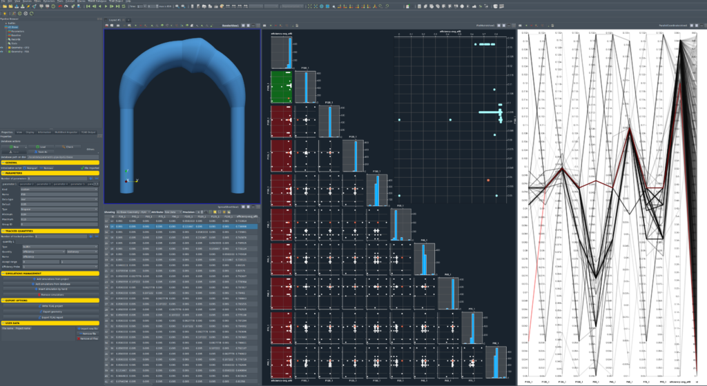
Knowledge Extraction
Beyond the Best Design
The optimized geometry is only one outcome of the study. The optimization process generated a complete dataset containing design variables, CFD results, and performance metrics for every evaluated design.
Design Space Exploration
The generated dataset can be used to identify parameter sensitivities, design trends, and performance correlations that would be difficult to discover from individual simulations.
Foundation for Surrogate Models
Once sufficient simulation data is available, surrogate models can be trained to predict performance almost instantly, enabling rapid design exploration and decision support.
Building Engineering Knowledge
By systematically capturing simulation inputs and outputs, optimization studies evolve from isolated projects into reusable engineering knowledge assets. TBASE can save results from multiple studies and create surrogate models without requiring expensive simulations.
Downloads & Resources
File name: parametric-pipe-optimization-TCAE-Tutorial.zip
File size: 0.4 MB
Tutorial Features: CFD, TCAE, TMESH, TCFD, SIMULATION, INCOMPRESSIBLE FLOW, STEADY-STATE, AUTOMATION, WORKFLOW, SNAPPYHEXMESH, 1 COMPONENT, 3D, Finite Volume, CFD, OpenFOAM, k-ω-SST
Related Knowledge & References
[1] Direct algorithm: https://optimization-online.org/wp-content/uploads/2005/08/1194.pdf
[2] TCAE Training
[3] TCAE Manual
[4] TCAE Webinars