Centrifugal Compressor Benchmark - HECC Stage
This benchmark shows a CFD workflow of a High-Efficiency Centrifugal Compressor Stage using a simulation environment TCAE
HECC Stage - Introduction
This benchmark study shows a step-by-step workflow of CFD validation of the centrifugal compressor. The simulation software used for this analysis is TCAE – a comprehensive simulation environment based on open source. This centrifugal compressor has been extensively tested in NASA laboratories and detailed reports are available [1], [2]. The physical measurements provide a lot of experimental data to support CFD validation. The goal of this study is to show in detail how to make a comprehensive simulation analysis of the two major centrifugal compressor characteristics: pressure ratio & efficiency vs. flow rate. The results are compared with the experimental data from two excellent papers [1] Medic, G., Sharma, O.P., Jongwook, J. at al. (2014) High Efficiency Centrifugal Compressor for Rotorcraft Applications, NASA/CR—2014-218114/REV1 and [2] Braunscheidel, Edward & Welch, Gerard & Skoch, Gary & Medic, Gorazd & Sharma, Om. (2014). Aerodynamic Performance of a High Efficiency Centrifugal Compressor at the Stage and Subcomponent Level. 10.2514/6.2014-3632.
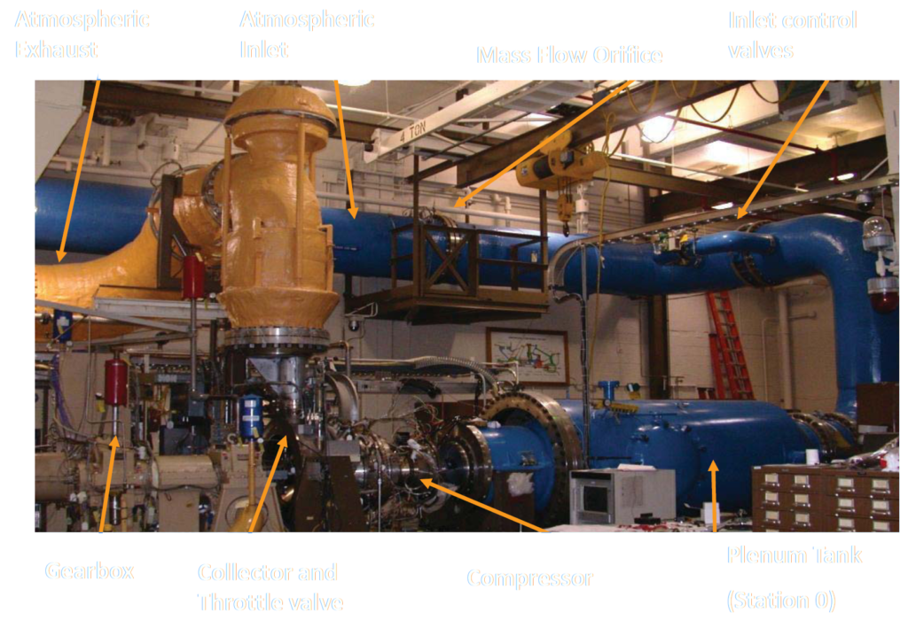
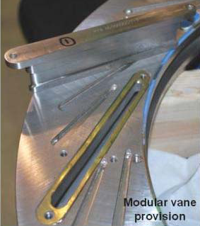
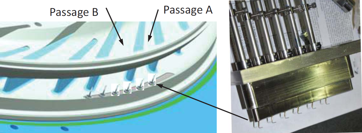
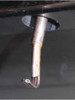
HECC testing was conducted in the NASA Small Engine Components Test Facility located at Glenn Research Center. The facility was operated with atmospheric intake and exhaust, and an orifice plate was used to determine the physical mass flow rate. Inlet valves located downstream of the orifice are used to set the plenum pressure. To minimize inlet flow field disturbances, the inlet piping has long radius elbows with turning vanes and the plenum tank contains a foreign object protection screen, downstream of which is the compressor inlet reference. More details about the measurement facility and strategy can be found in [1].
HECC Stage - Geometry Description
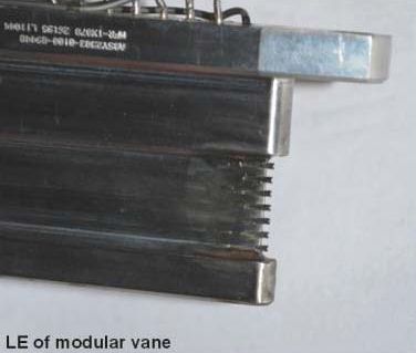
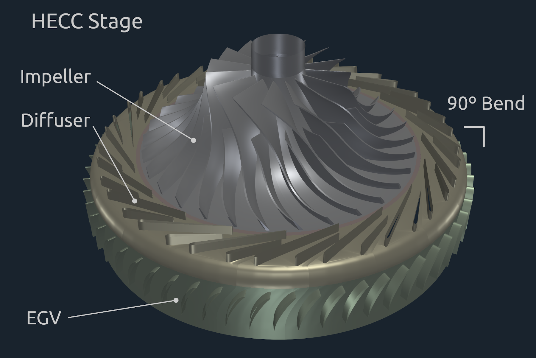
The centrifugal compressor (HECC Stage) geometry is described in the following sketch. The HECC stage comprises a splittered impeller, splittered diffuser, 90-deg. bend, and EGV blade row. The impeller has 15 main-blade/splitter-blade pairs with a spanwise varying backsweep between 32 to 42 deg. from radial, and with -2 deg. axial lean at the leading edge and -29 deg. axial lean at the trailing edge. The impeller blades have elliptical leading edges. Trailing edges are also elliptical which differs from the typically blunter trailing edges of trimmed impellers. The vaned diffuser comprises 20 main/splitter vane pairs with the splitters slightly offset to maximize pressure recovery. The EGV blade row comprises 60 cascade-style airfoils. The design speed is Nc = 21,789 RPM, corrected to inlet conditions, resulting in an impeller exit speed of U2 = 492 m/s. The detailed dimensions and physical features of the compressor are provided in [2].
Centrifugal Compressor - Simulation Input
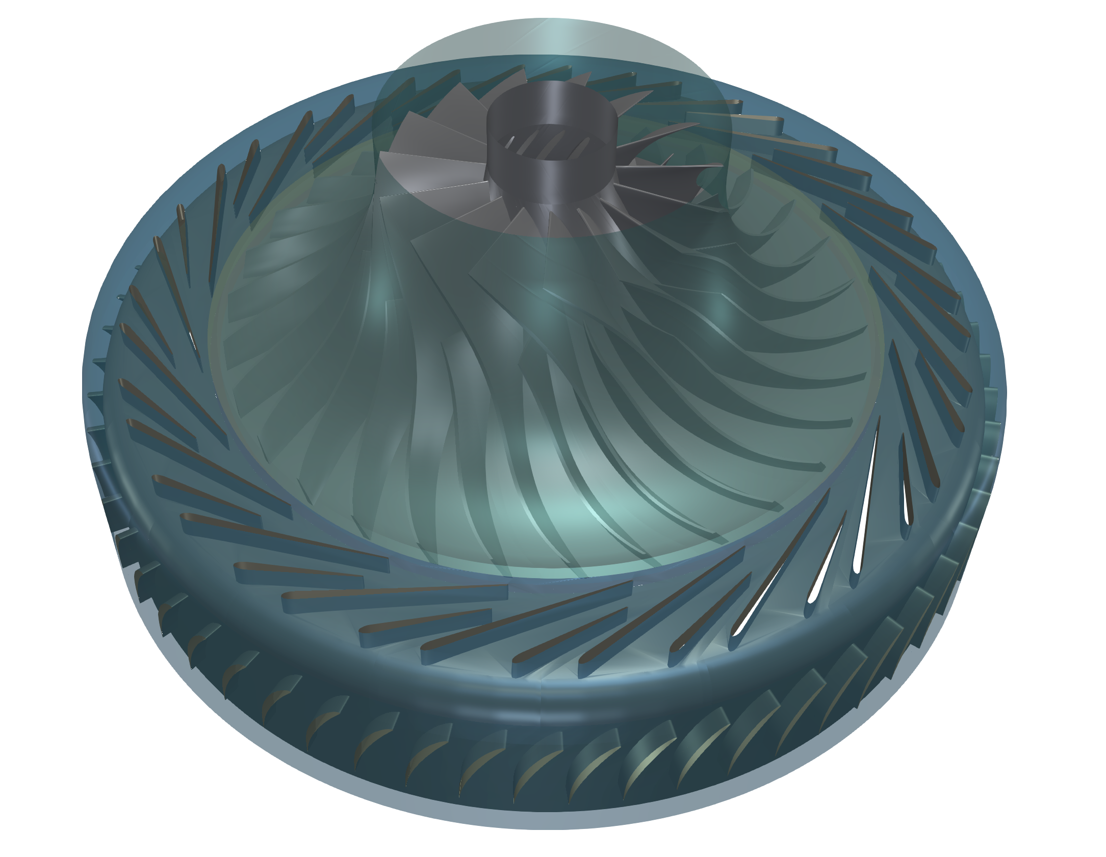
A typical input for a detailed simulation analysis is a 3D surface model in form of an STL surface. For CFD simulation, it is needed to have a simulation-ready surface, which is a closed watertight model (sometimes also called waterproof, or model negative, or wet surface) of the model inner parts where the fluid flows. Similarly, for FEA simulation, it is needed to have a closed surface model of the solid of the impeller in form of a single STL surface.
In general, there are multiple ways how the CAD model can be created. The CAD model of the CAD can be generally created in any CAD software manually or in an automated way via a parametric model.
For general turbomachinery, engineers can use special dedicated software for turbomachinery design like for example CFturbo, Concepts NREC, or TURBOdesign Suite and create the CAD model and export STL surface. Alternatively, the surface model of a centrifugal compressor can be created in open-source software like Salome, FreeCAD, or OpenCascade.
In any case, a compressor can be described with the help of a set of parameters that describe all its important shapes and measures. The parameters can be later modified and optimized in an automated optimization loop.
An existing CAD model is typically received in the STEP or IGES CAD file format. Original CAD files are usually too complex for comprehensive CFD and FEA simulations, so certain preprocessing (cleaning) CAD work is generally needed. While the original CAD model for this project was simplified and cleaned using Salome open-source software, any other standard CAD system can be used instead.
HECC Stage - CFD Preprocessing
For CFD simulation it is best to split the geometry into several waterproof components because of rotation (some parts may be rotating and others not). Each component itself has to be waterproof and consists of a few or multiple STL surfaces. It is smart to split each component into multiple surfaces (more is better) because it opens a broader range of meshing options, simulation methods (mesh refinements, manipulation, boundary conditions, evaluation of results on model-specific parts, …), and postprocessing.
The principle is always the same: the 3D surface model has to be created; all the tiny, irrelevant, and problematic model parts must be removed, and all the holes must be sealed up (a watertight surface model is required). This centrifugal compressor CAD model is reasonably simple. The final surface model in the STL format is created as input for the meshing phase. This preprocessing phase of the workflow is extremely important because it determines the simulation potential and limits the CFD results.
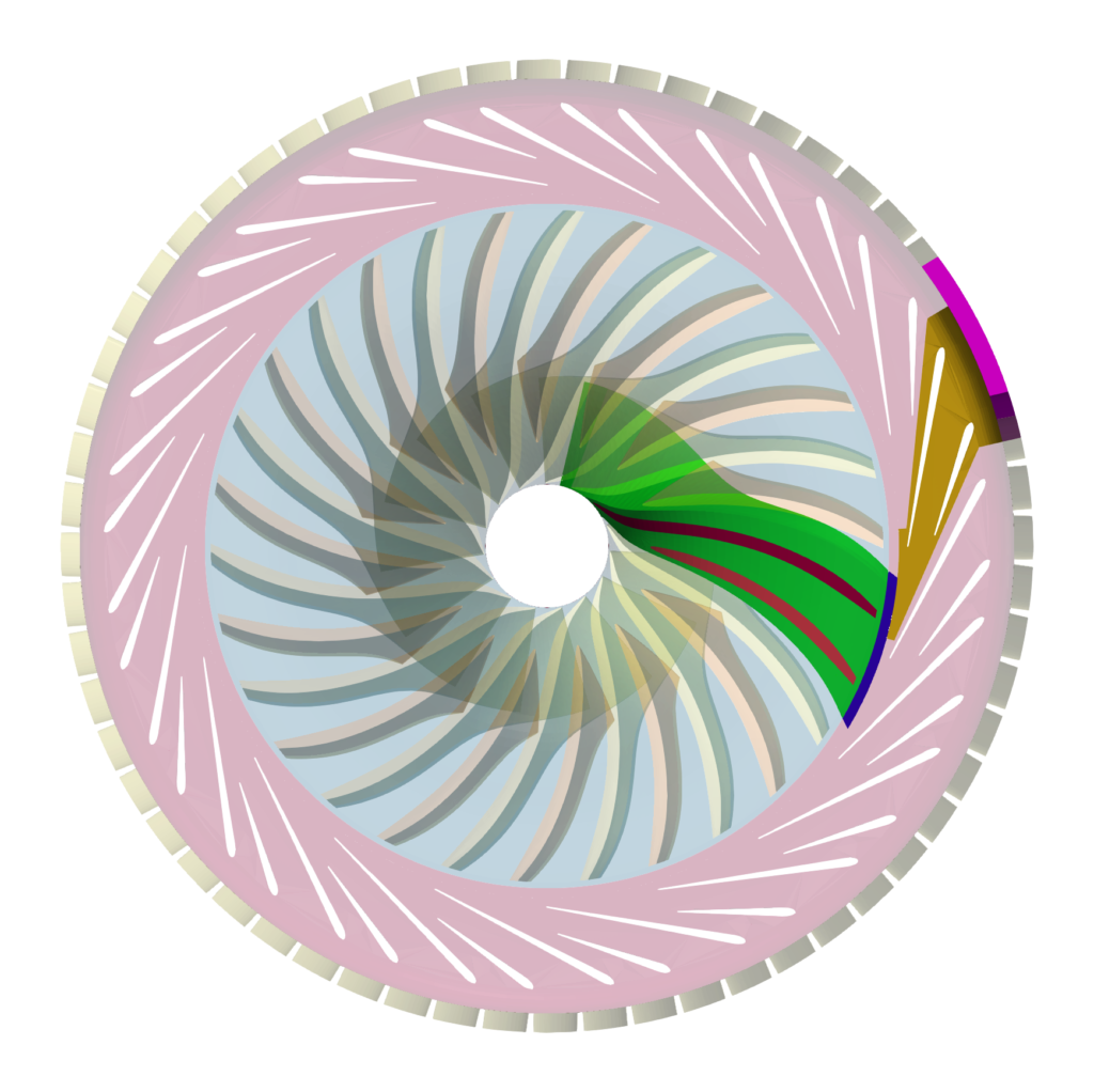
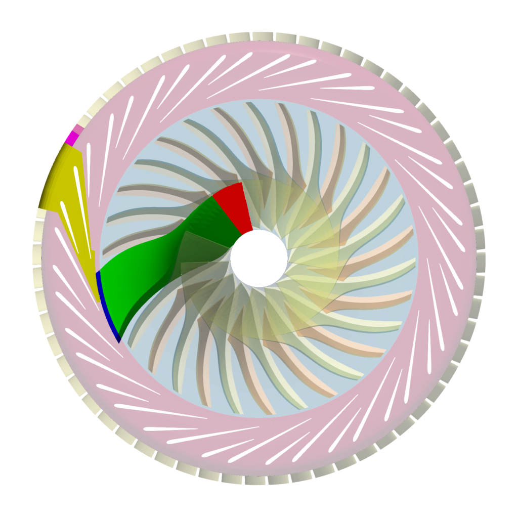
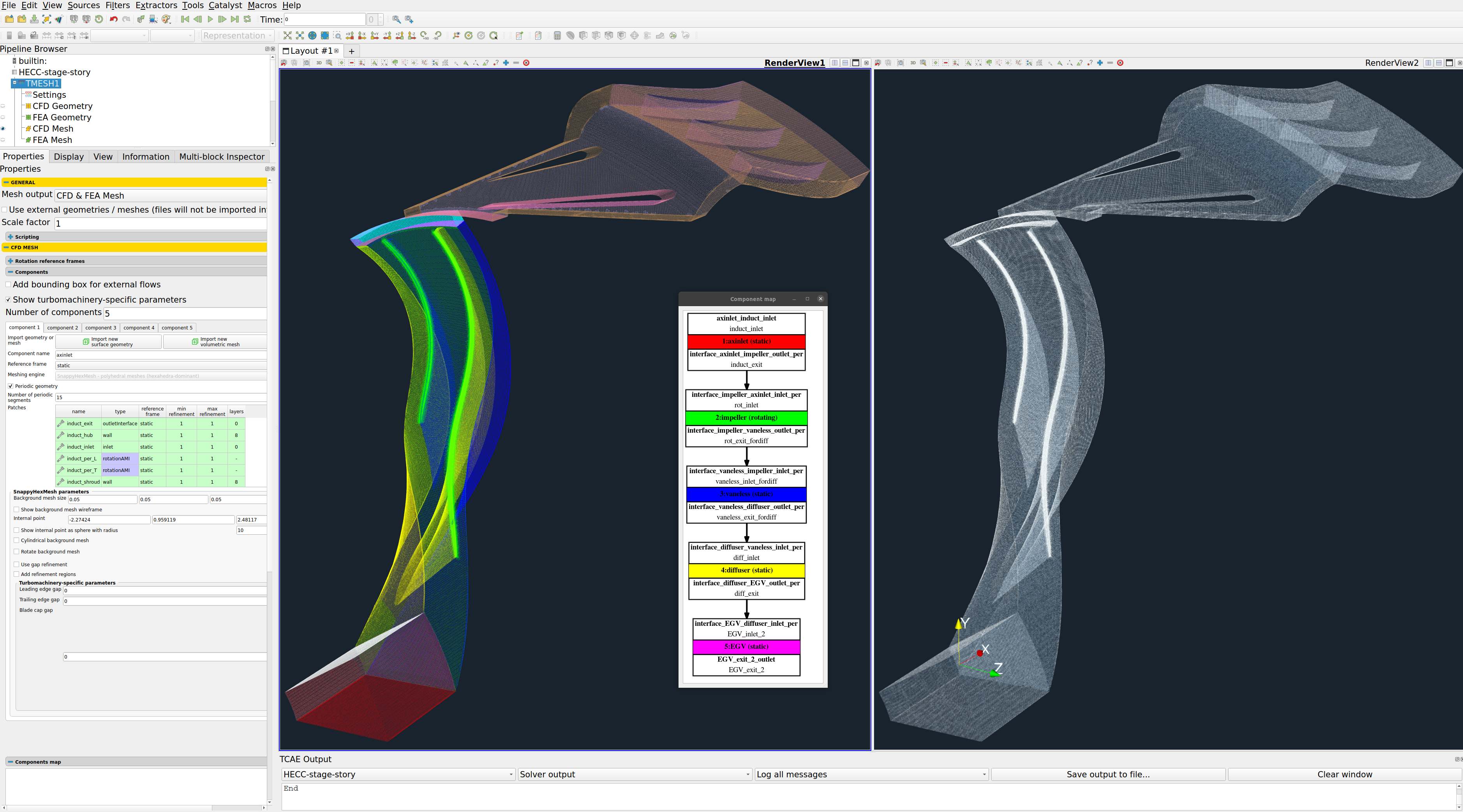
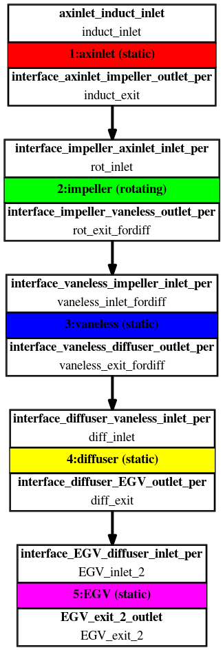
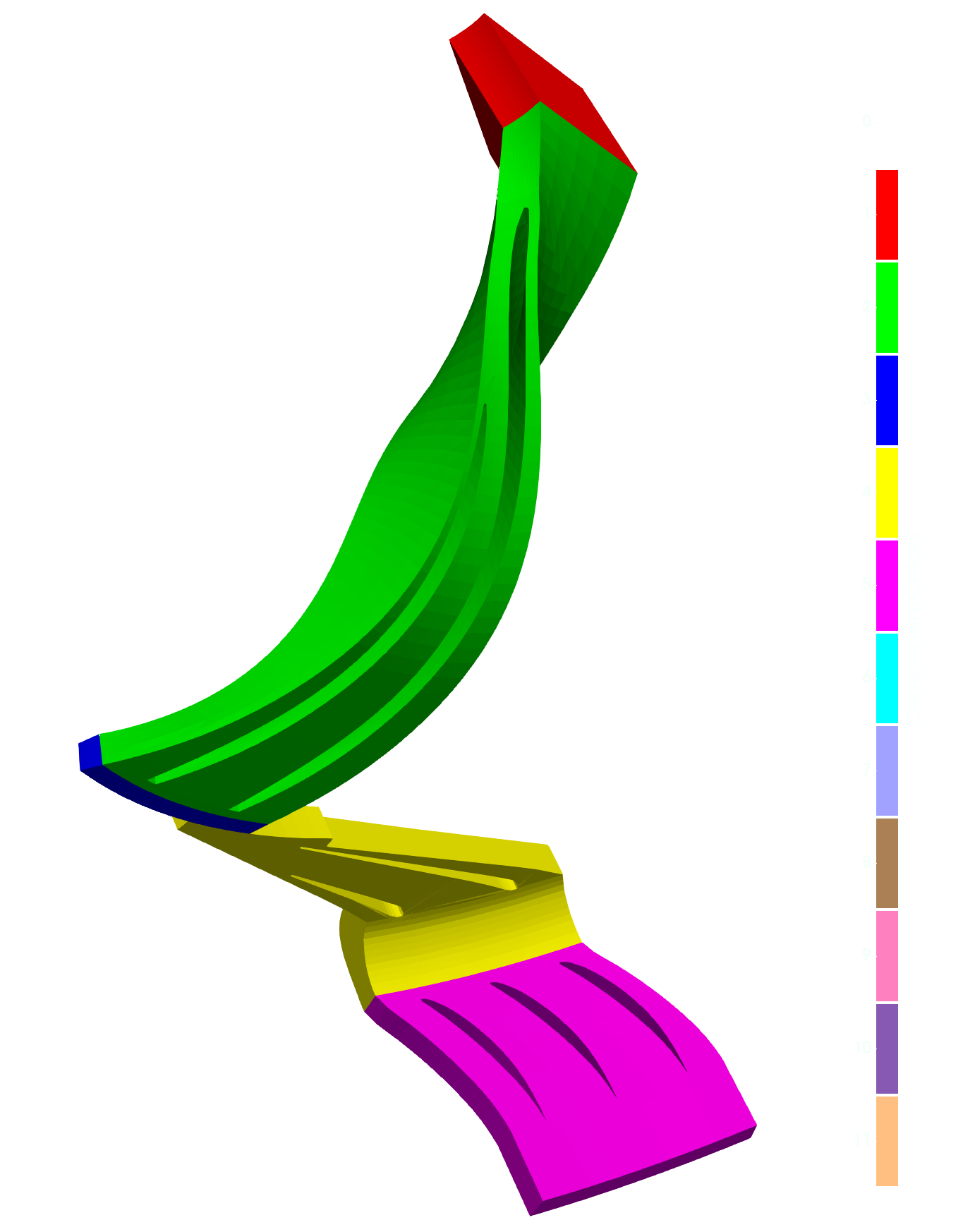
In this centrifugal compressor project, the CAD model was split into five logical parts: Axial Inlet tube, Impeller, Veneless Extension, Diffuser and EGV. Each compressor part (model component) is watertight and includes its own inlet interface, outlet interface, and corresponding walls (wall, blade, hub, shroud, fillets, stator blades, vane blades, …). At first, each individual component is created its own volume mesh, and after that, in the simulation process, the component meshes are merged into a single mesh by the TCAE processor. The components are joined via interfaces. The component interfaces should fit each other topologically, while the meshes are typically different from both sides. In the case of using the Mixing Plane interface, the interface match is not necessary.
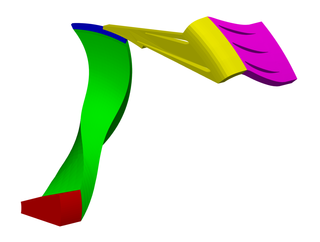
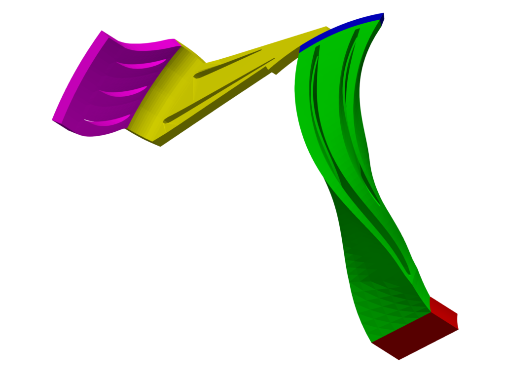
The surface model data in .stl file format together with physical inputs are loaded in TCFD. Another option would be loading an external mesh in OpenFOAM mesh format or loading an MSH mesh format (Fluent mesh format), or CGNS mesh format. This CFD methodology employs a multi-component approach, which means the model is split into a certain number of components. In TCFD each region can have its own mesh and individual meshes communicate via interfaces. This particular HECC stage is perfectly rotationally symmetric (its meridian never changes circumferentially) and the number of blades is relatively high (15 main and splitter impeller blades, 20 main and secondary diffuser vanes, 60 EGV blades). For those reasons, this particular case is very suitable for simulating just a periodic segment. Five components have been selected. 1. Axial inlet. 2. Impeller 3. Vaneless extension 4. Diffuser 5. EGV.
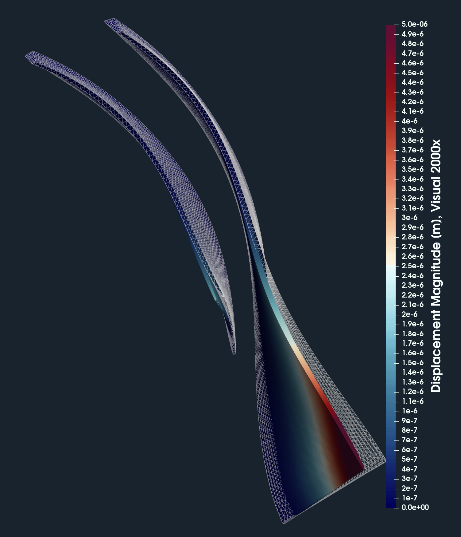
HECC Stage - FEA Preprocessing
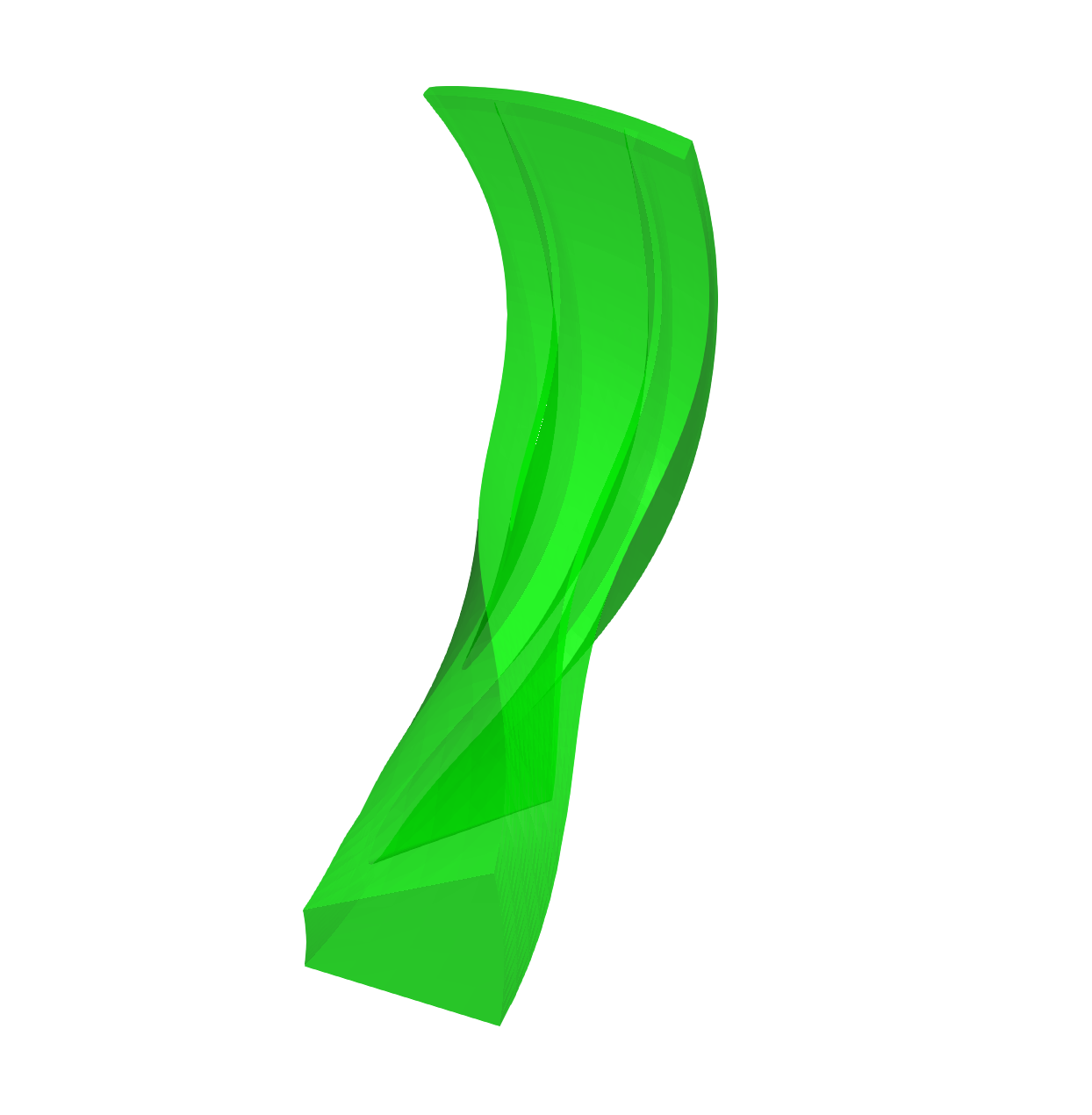
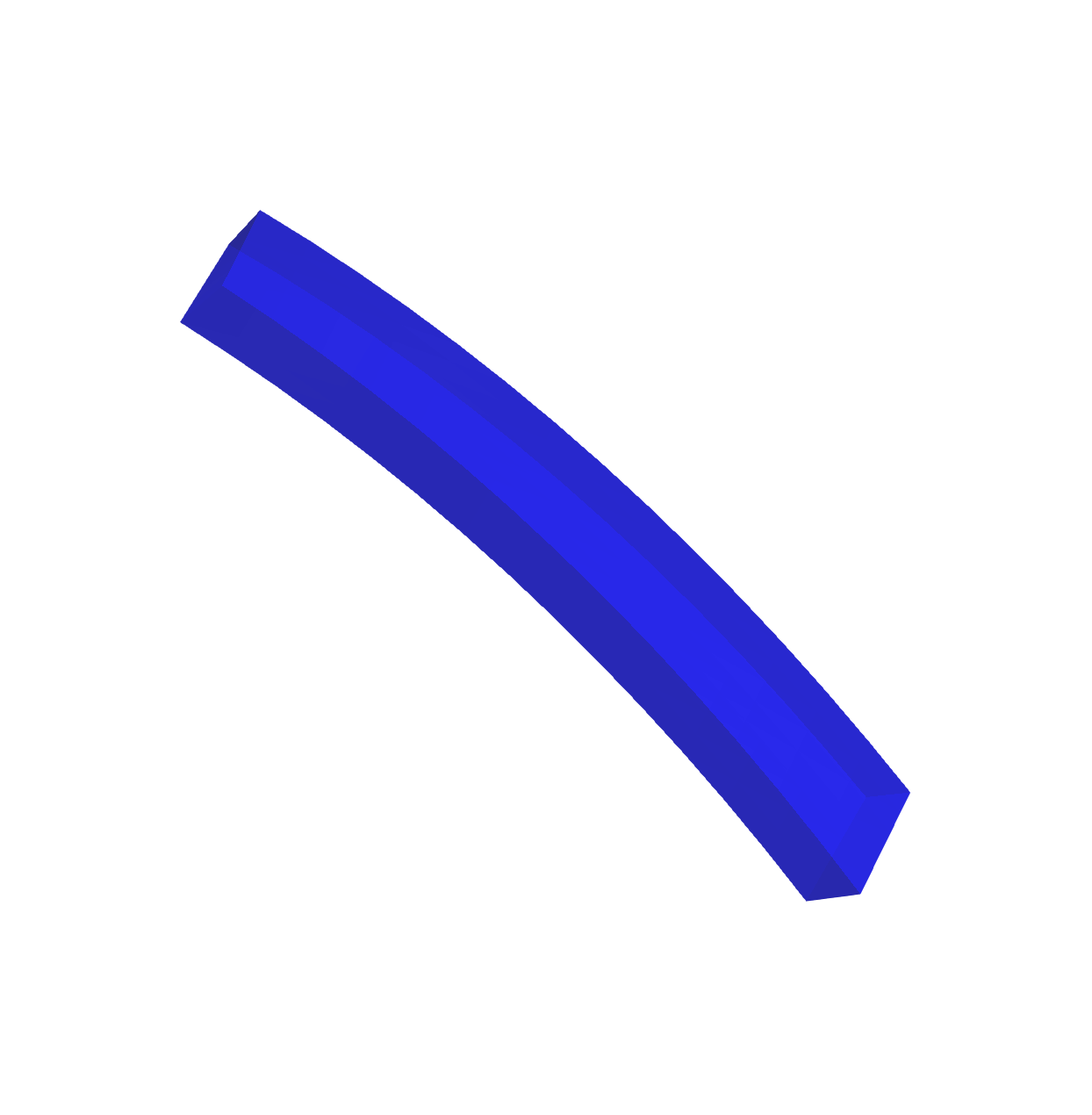
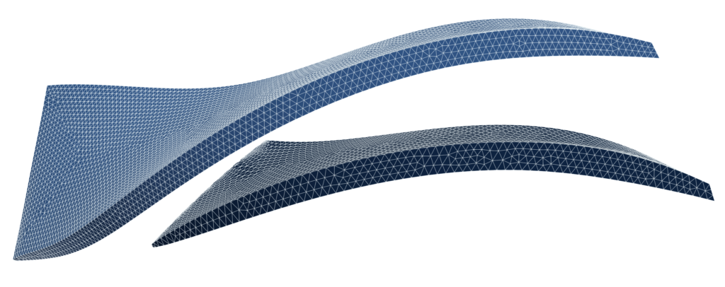
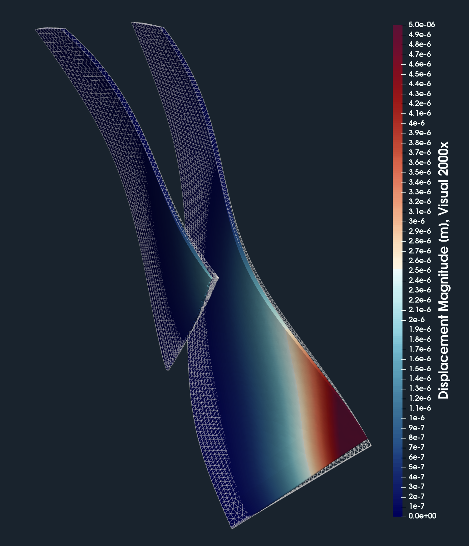
For FEA preprocessing, the rules are similar to CFD preprocessing and cleaning. It is best to create a simple, single, waterproof STL surface of the solid. After that, the model is ready for meshing with the TMESH module using NetGen or Gmsh open-source application. In this particular study, the compressor impeller is investigated. It consists of two components: the splitter blade and the main blade.


IMPORTANT NOTICE ON PREPROCESSING
The surface of the simulation-ready model has to be clean, simple enough but not simpler! The principles are always the same: the watertight surface model has to be created; all the tiny, irrelevant, and problematic model parts must be removed, and all the holes must be sealed up (the watertight surface model is required). The preprocessing phase is an extremely important part of each simulation workflow. It sets up all the simulation potential and limitations. It should never be underestimated. Mistakes or poor quality engineering in the preprocessing phase can be hardly compensated later in the simulation phase and postprocessing phase. For more details, see the TCAE documentation.
HECC Stage - CFD Meshing
The computational mesh for CFD is created in an automated software module TMESH, using the snappyHexMesh open-source application. All the mesh settings are done in the TCAE GUI.
For each model component, a cartesian block mesh is created (box around the model), as an initial background mesh, that is further refined along with the simulated object. Basic mesh cell size is a cube defined with the keyword “background mesh size”.
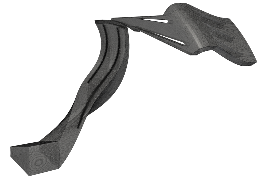
The mesh is gradually refined to the model wall. The mesh refinement levels can be easily changed, to obtain the coarser or finer mesh, to better handle the mesh size. Inflation layers can be easily handled if needed. The final mesh statistics are following:
Number of cells: Axial inlet: 207547; impeller: 4217674; vaneless: 331988; diffuser: 607453; EGV : 475608; Total cells: 5840270. Including 8 inflation layers on walls.
HECC Stage - FEA Meshing
The computational mesh for FEA is created in an automated software module TMESH, using the NetGen open-source application. All the mesh settings are done in the TCAE GUI.

The closed STL model has been meshed with just a little effort because there are just a few parameters to set. The most important parameters for FEA meshing are “h Max” and “h Min” which mean the maximal and minimal mesh edge in meters. The mesh is created with an automated algorithm.
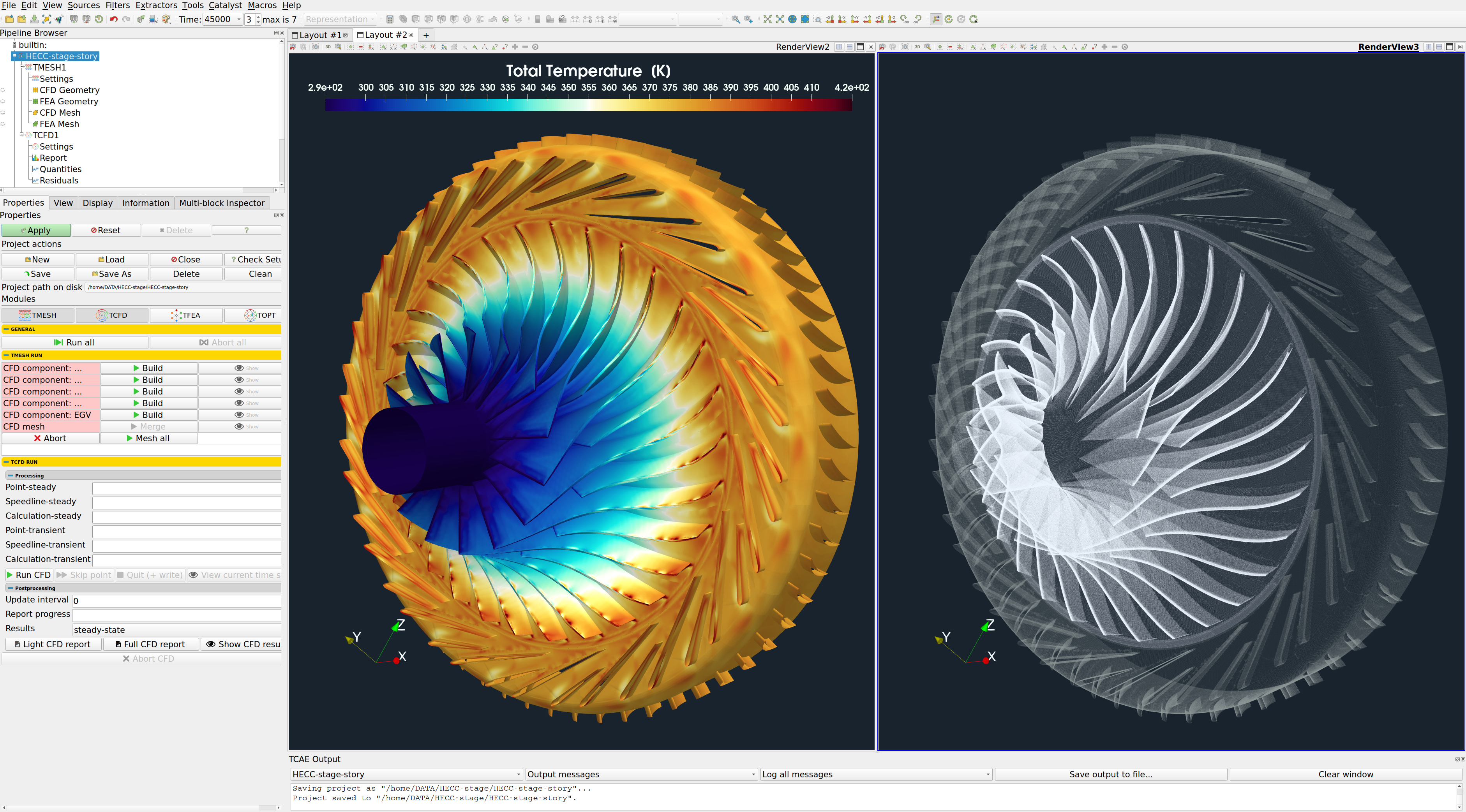
HECC Stage - CFD Simulation Setup
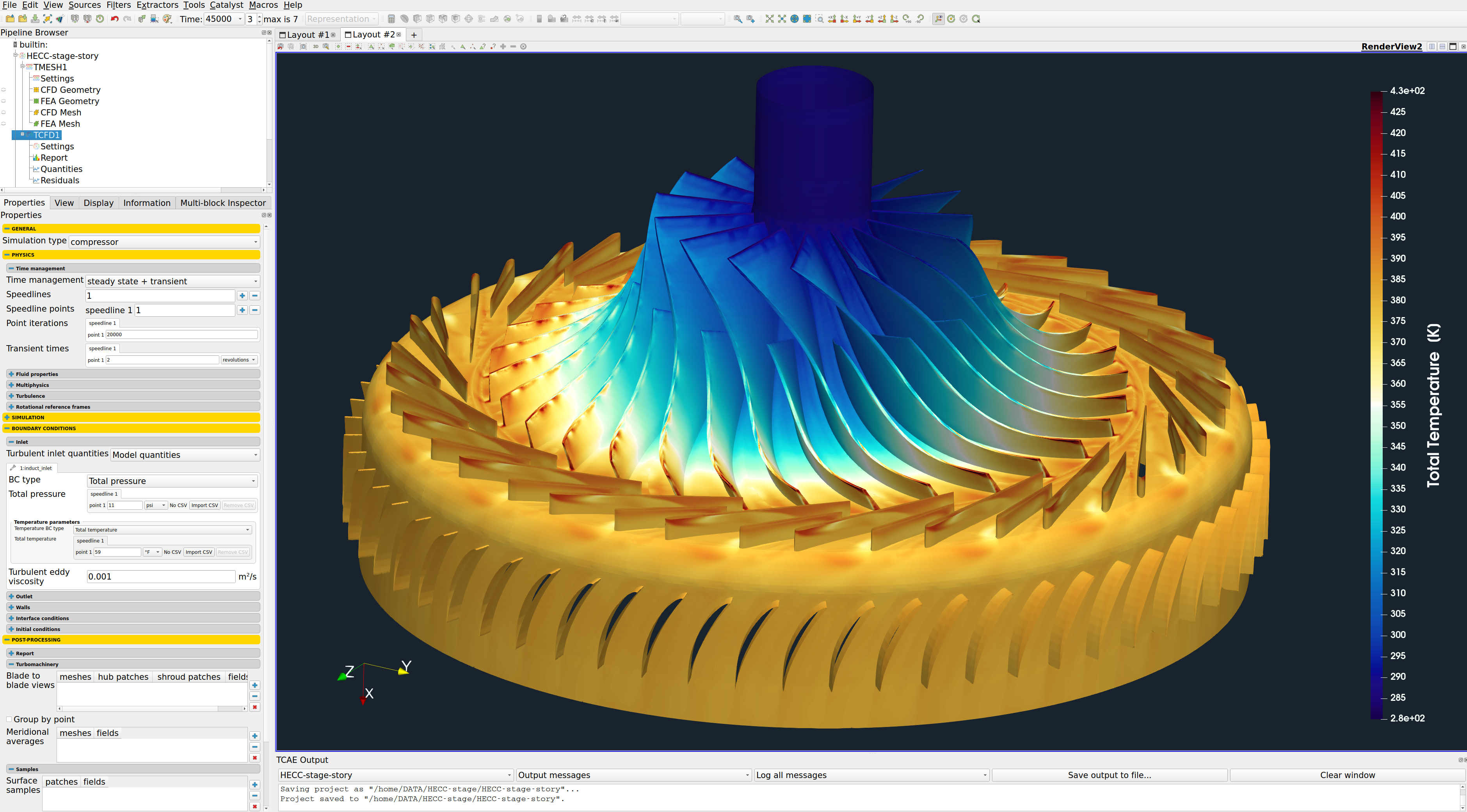
The CFD simulation is managed with TCAE software module TCFD. Complete CFD simulation setup and run is done in the TCFD GUI in ParaView. TCFD uses solvers based on OpenFOAM open-source software.
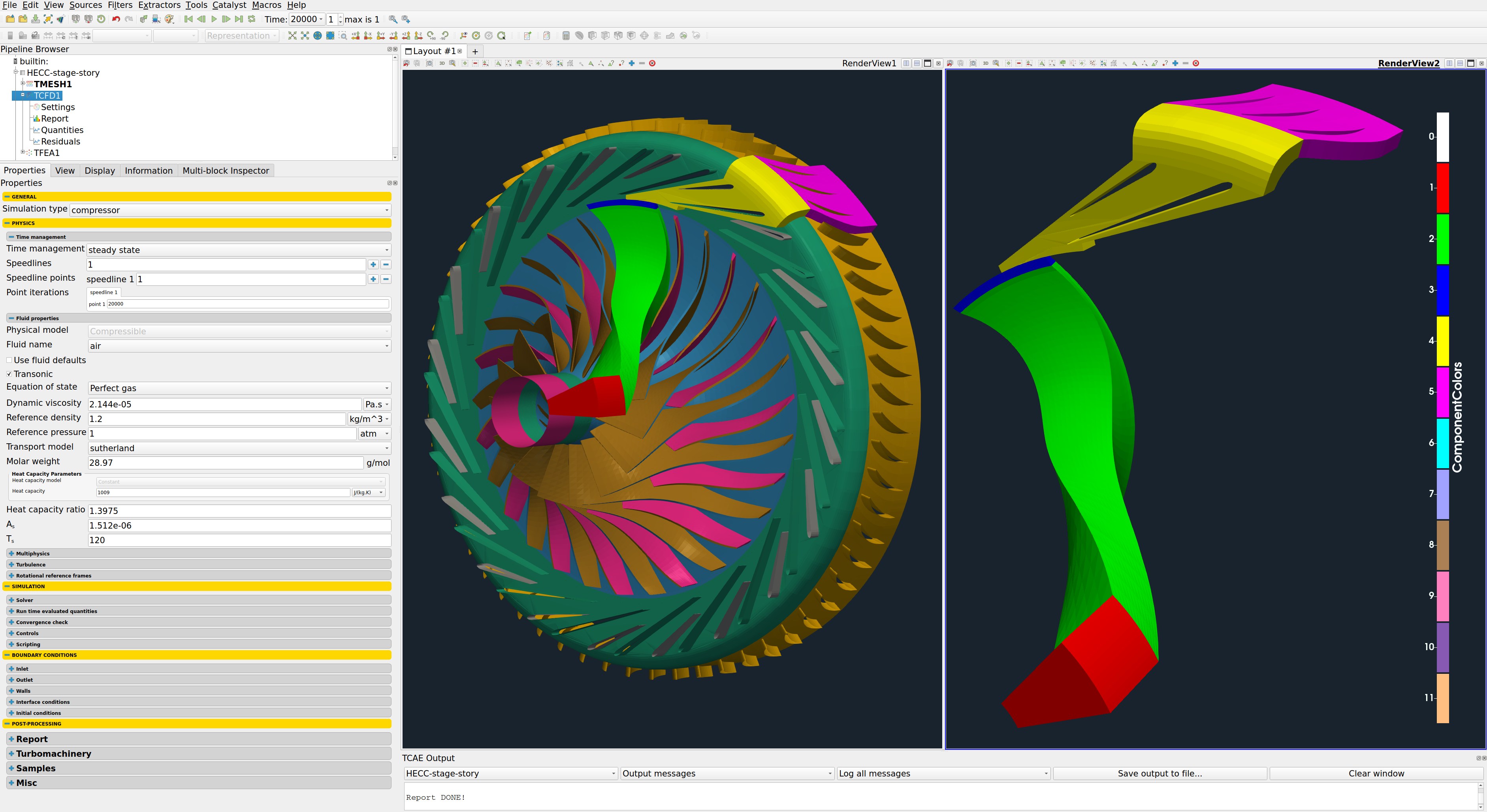
- Simulation type: compressor
- Time management: steady-state
- Physical model: Compressible
- Number of components: 5 [-]
- Wall roughness: none
- Speed: 21789 [RPM]
- Outlet: variable static pressure [m2/s2]
- Turbulence: RANS
- Turbulence model: k-omega SST
- Shear Thinnig model: Newtonian
- Wall treatment: Wall functions
- Turbulence intensity: 5%
- Speedlines: 4 [-]
- Simulation points: 44 [-]
- Fluid: Air
- Reference pressure: 1 [atm]
- Dynamic viscosity: 2.144 × 10E-5 [Pa⋅s]
- Reference density: 1.2 [kg/m3]
- CFD CPU Time: 372 core.hours/point
- BladeToBlade: on
Every project simulated in TCFD has its component graph. The component graph is a simple scheme that shows how the components are organized. The flow model topology, the inlet, the outlet, and how the components are connected via interfaces. The component graph is shown below.
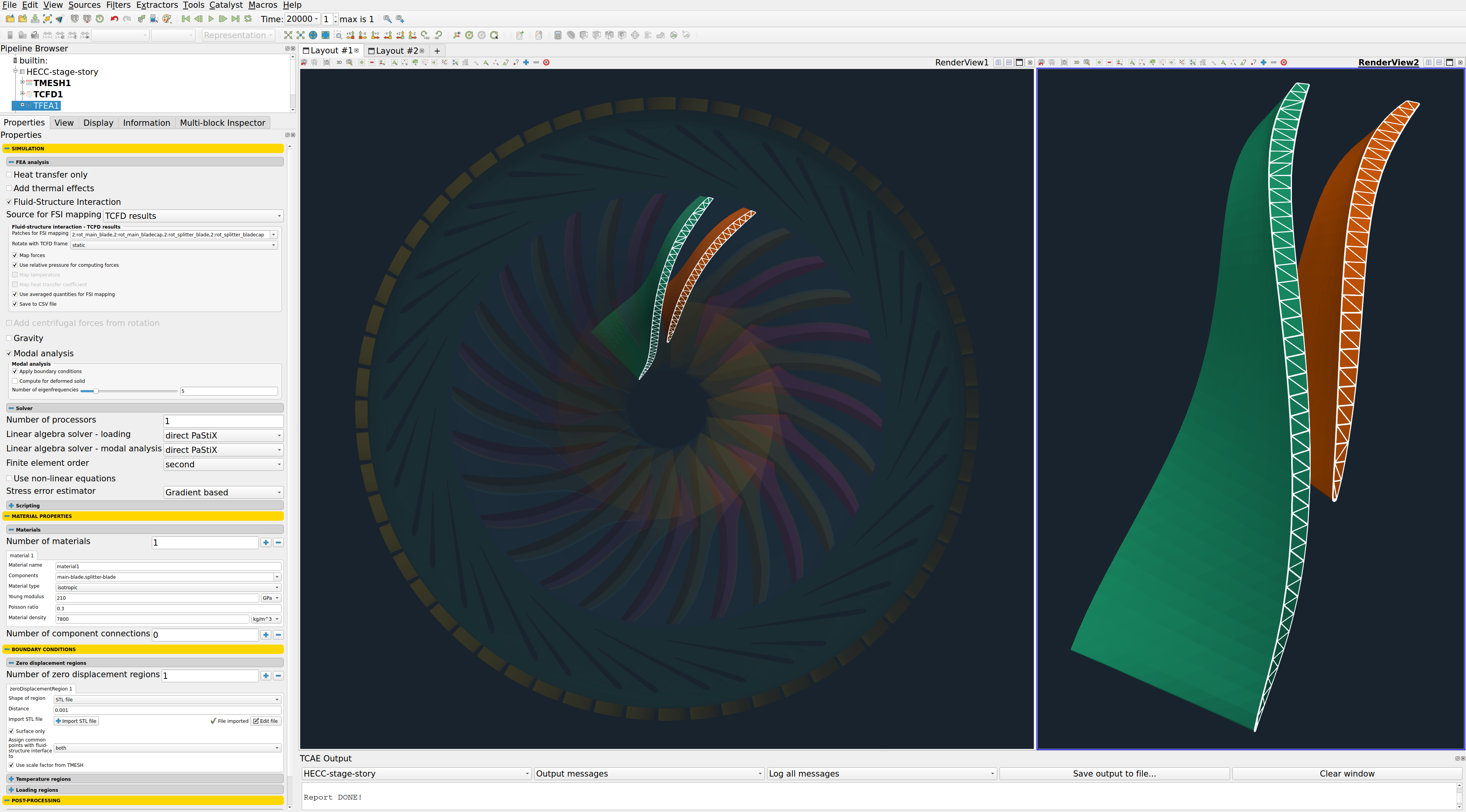
HECC Stage - FEA Simulation Setup
The FEA simulation is managed with TCAE software module TFEA. Complete FEA simulation setup and run are done in the TFEA GUI in ParaView. TFEA is based on the Calculix open-source application.
- Impeller material: Titanium Alloy 6AL-4V
- Material structure: isotropic
- Young modulus: 110E9 Pa
- Material density: 4480 kg/m3
- FSI source: TCFD [-]
- Poisson ratio: 0.34
- Fixed area: hub caps [mm]
- Finite element order: second
- FEA CPU Time: 0.1 core.hours/point
- Speed of rotation: 15252 [RPM]
HECC Stage - TCAE Simulation Run
The TCAE simulation run is completely automated. The whole workflow can be run by a single click in the GUI, or the whole process can be run in batch mode on a background. Modules used in this particular project are TCAD, TMESH, TCFD, and TFEA. The simulation is executed in the steady-state mode, for four speed-lines with total 44 points as they were measured in the experiment [1].
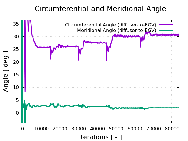
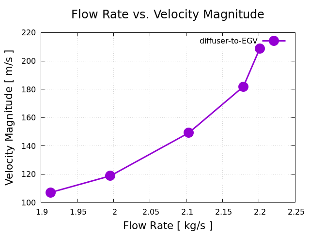
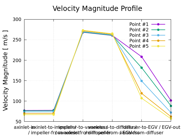
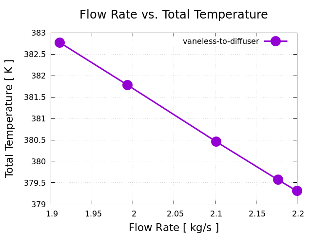
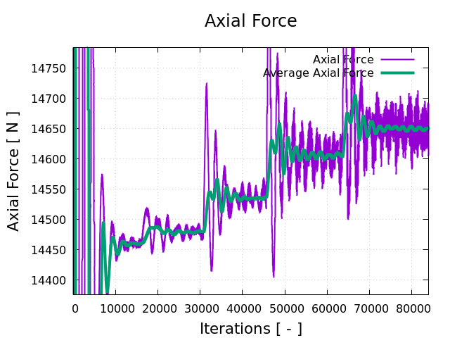
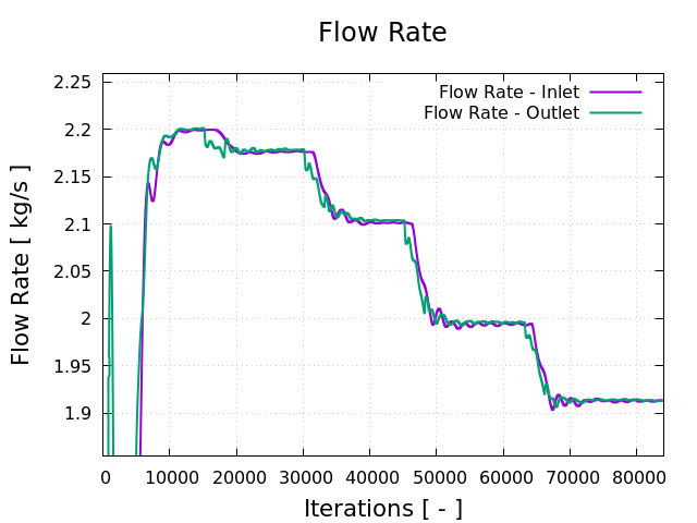
TCFD includes a built-in post-processing module that automatically evaluates all the required quantities, such as efficiency, torque, forces, force coefficients, flow rates, pressure, velocity, and much more. All these quantities are evaluated throughout the simulation run, and all the important data is summarized in an HTML report, which can be updated anytime during the simulation, for every run.
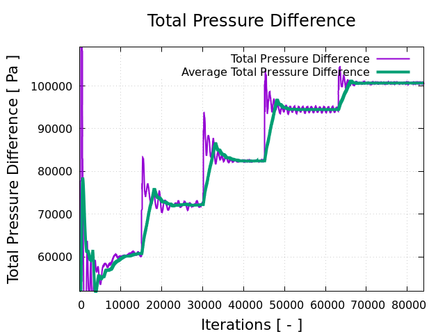
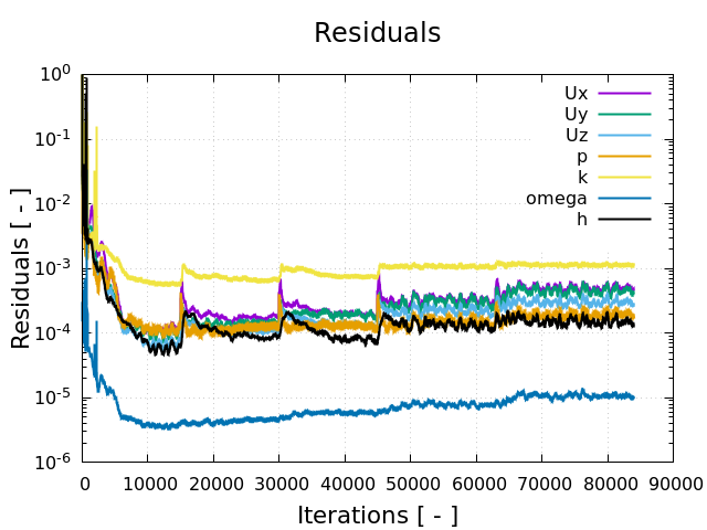
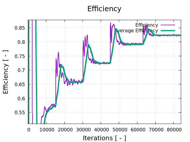
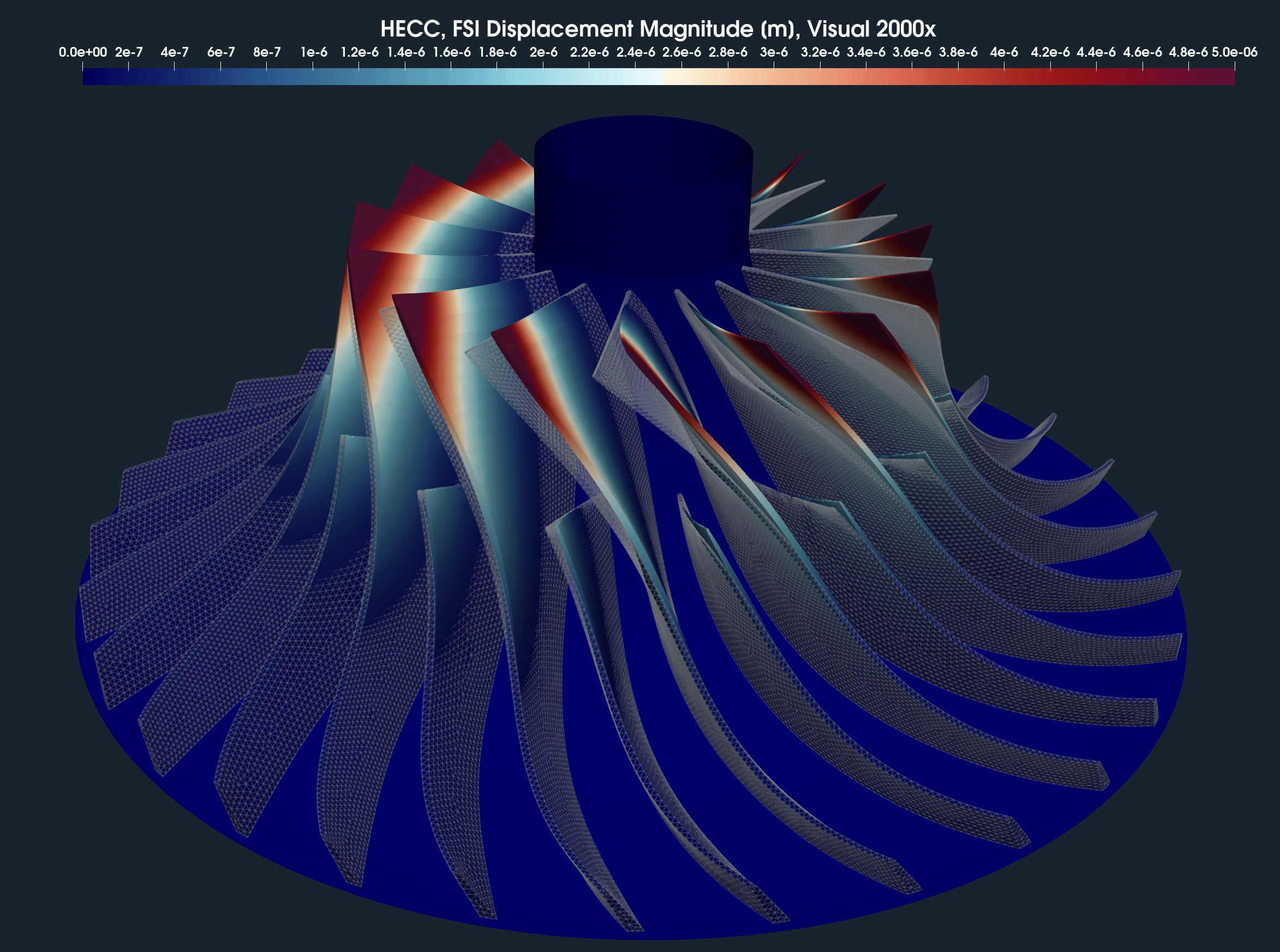
All the simulation data are also saved in tabulated .csv files for further evaluation. TCFD is capable of writing the results down at any time during the simulation. The convergence of basic quantities and integral quantities are monitored still during the simulation run. The geometry was created one-time using TCAD in the preprocessing phase. First, the TMESH is executed to create the volume meshes for CFD & FEA. Then the CFD simulation is executed and evaluated. After that, in the FSI step, the pressure field is integrated to create the force field which is prescribed as a load for the FEA simulation. Finally, the FEA simulation is executed and evaluated.
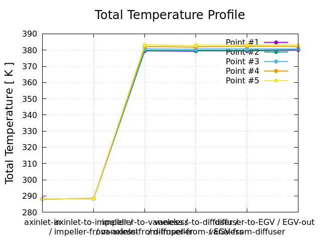
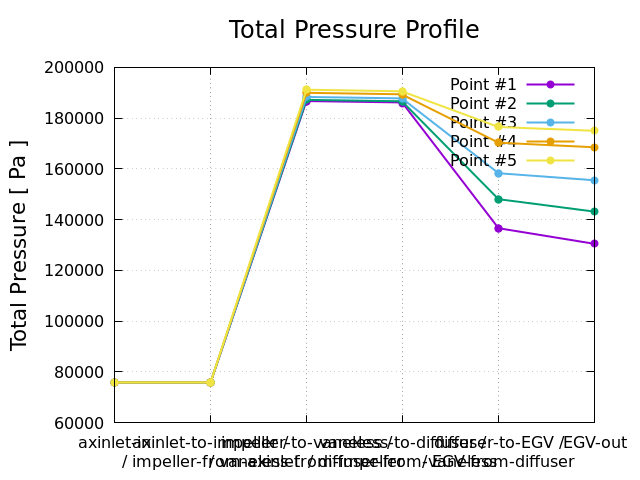
HECC Stage - Postprocessing - Integral Results
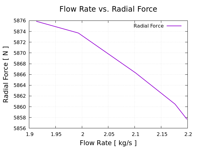
The integral results and simulation statistics are evaluated automatically for every simulation run. Every simulation run in TCAE has its own unique simulation report. The integral results both for CFD and FEA are written down in the corresponding HTML or PDF reports.
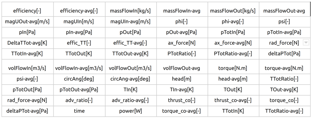
All the relevant integral quantities are evaluated, sorted, and stored in the corresponding CSV files and are ready for further usage. Following integral quantities are evaluated every time step.
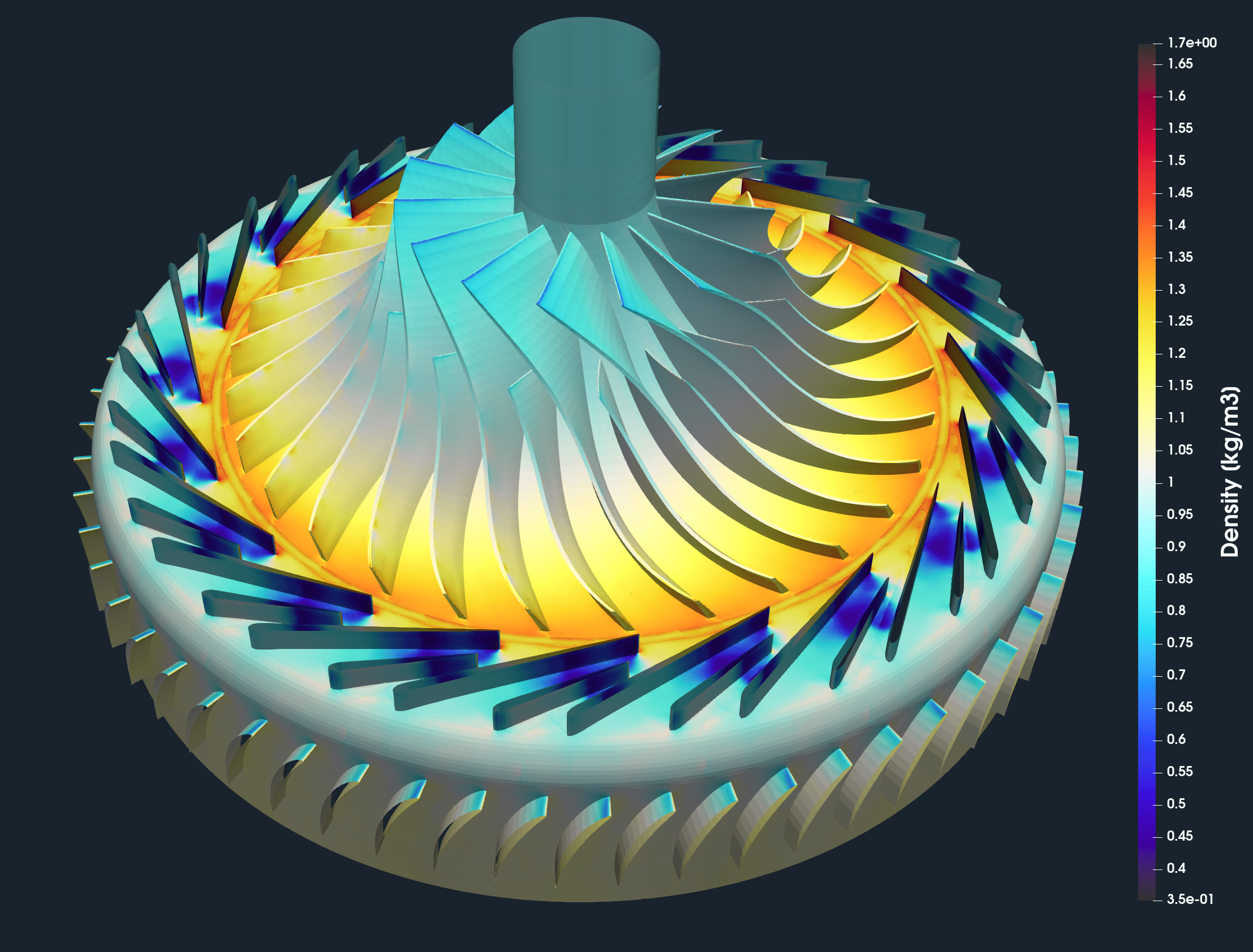
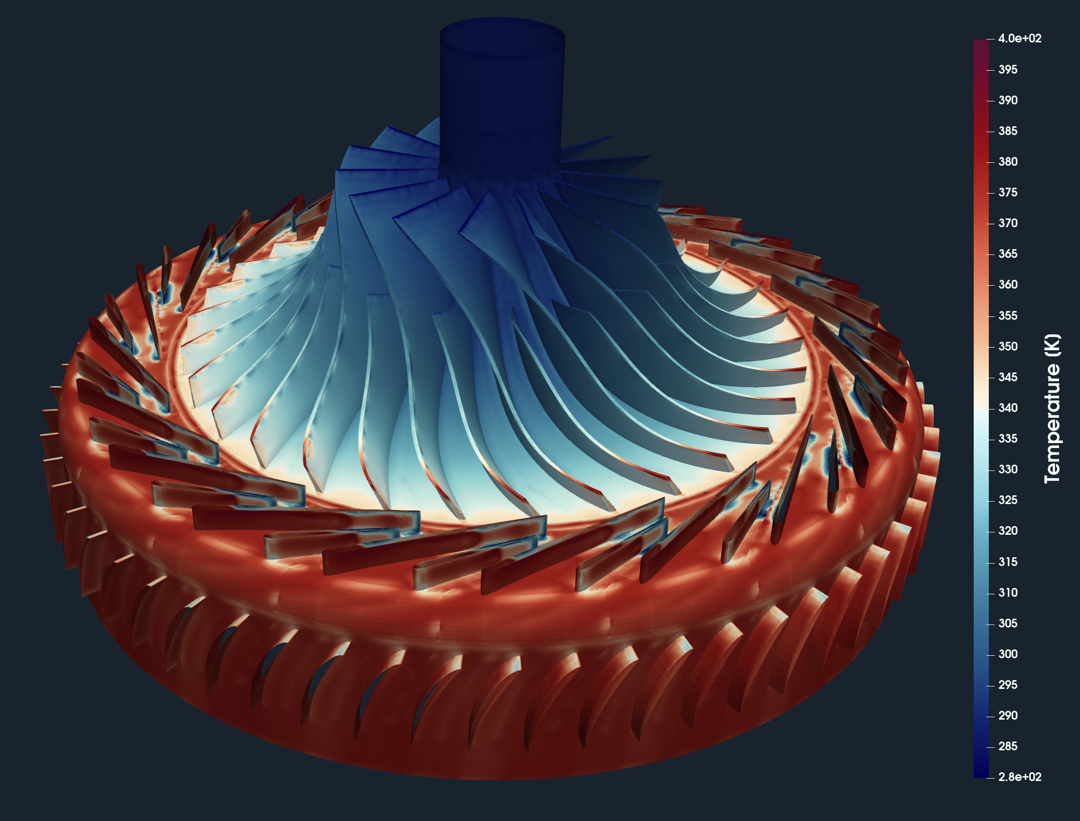
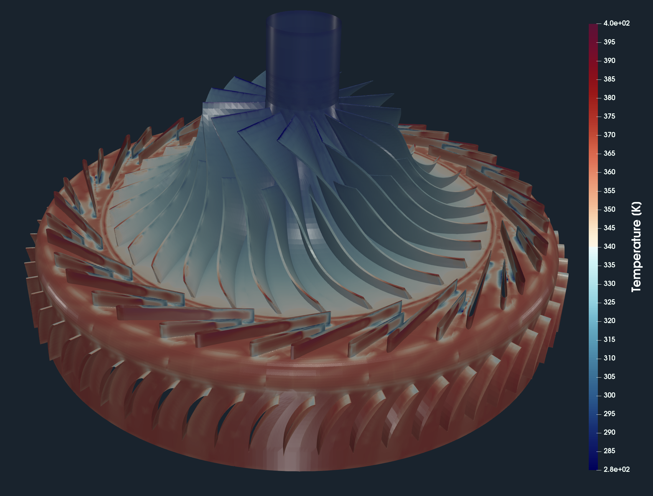
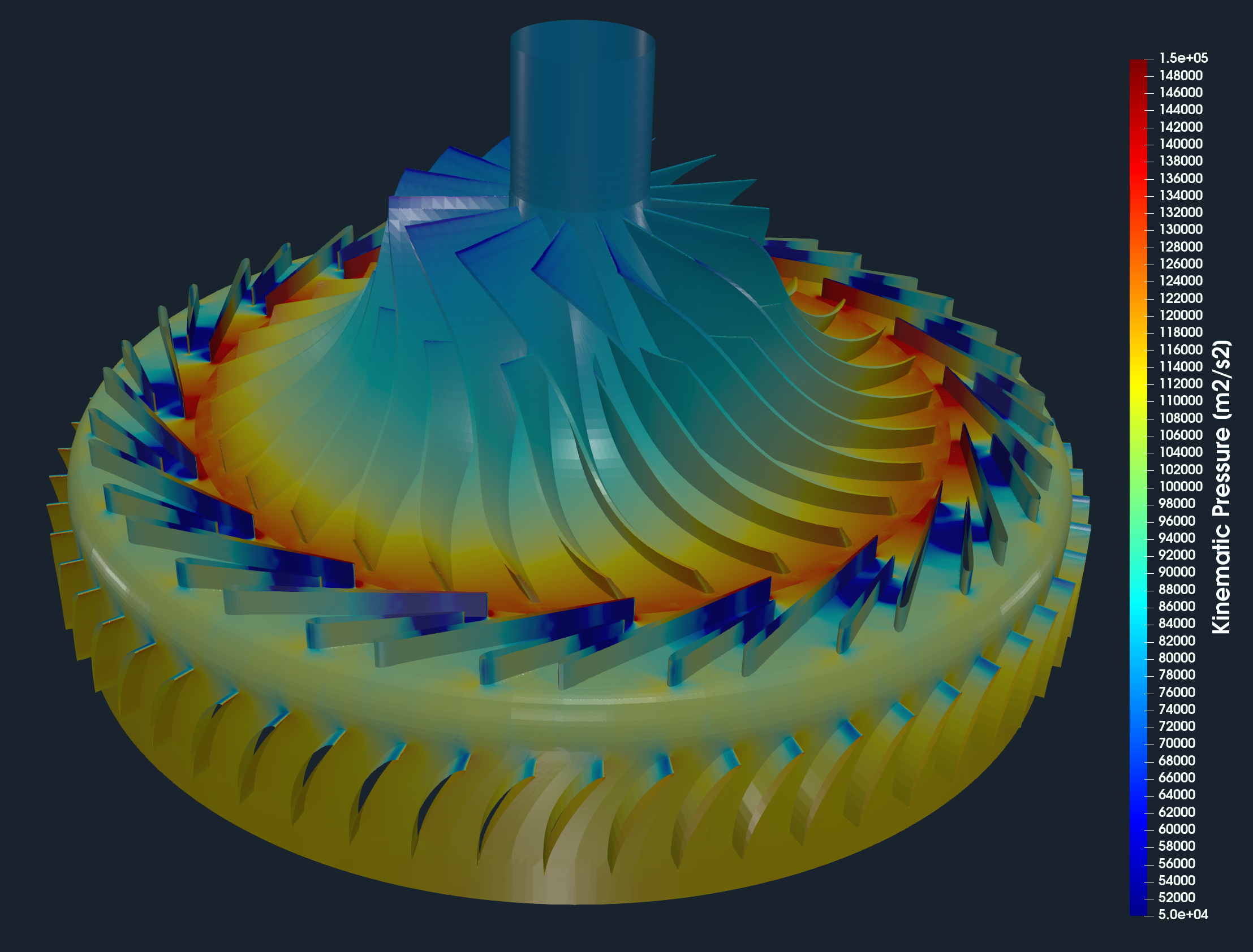
HECC Stage - Postprocessing - Volume Fields
While all the integral results are stored in the CSV files and are available for further postprocessing, the volume fields are post-processed in the open-source visualization tool ParaView. ParaView provides a wide range of tools and methods for CFD & FEA postprocessing and results evaluation. There are available countless useful filters and sources, for example, Calculator, Contour, Clip, Slice, Threshold, Glyph (Vectors), Streamtraces (Streamlines), and many others.
CFD Volume Fields
HECC Stage - Postprocessing - Turbomachinery Specific Views
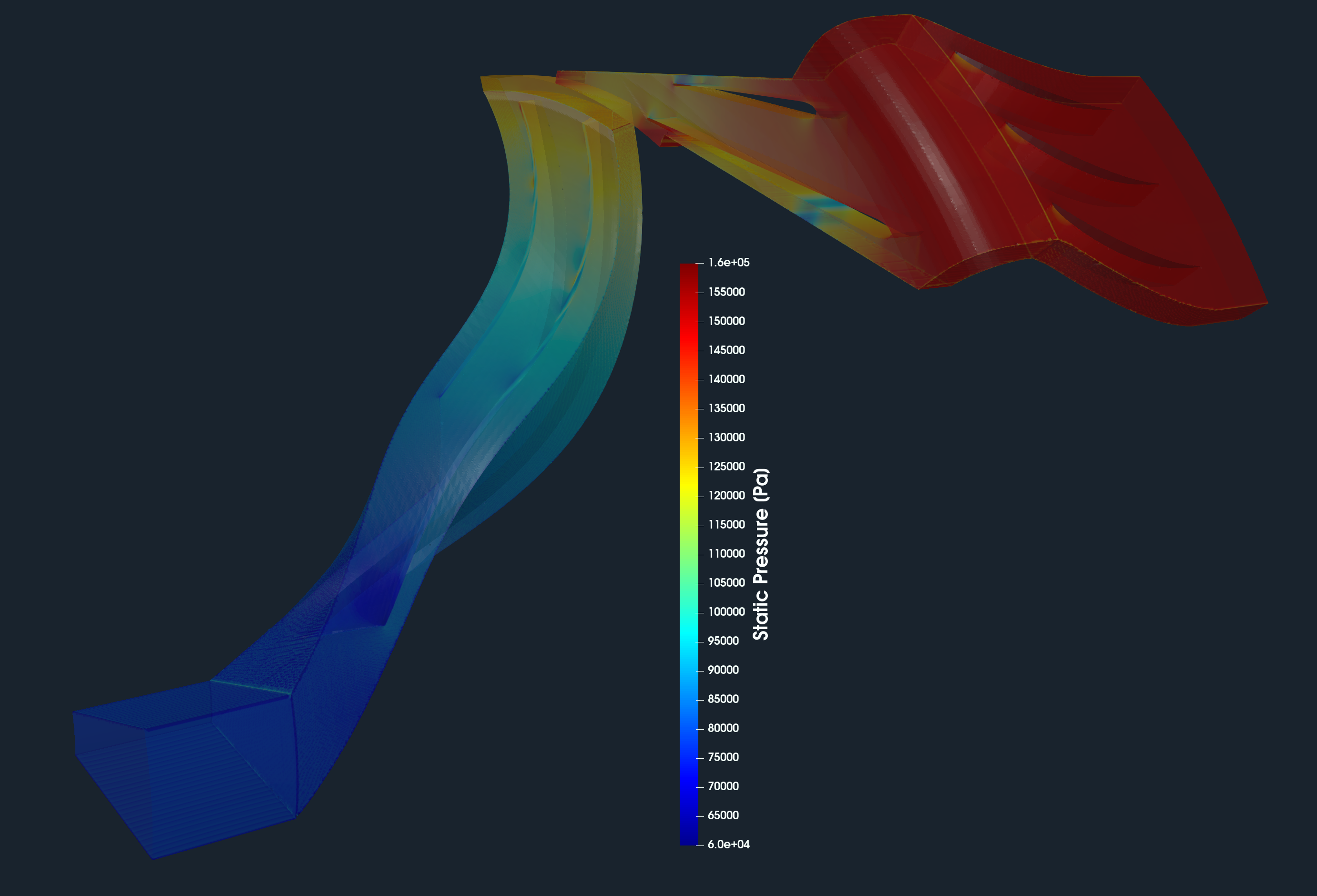
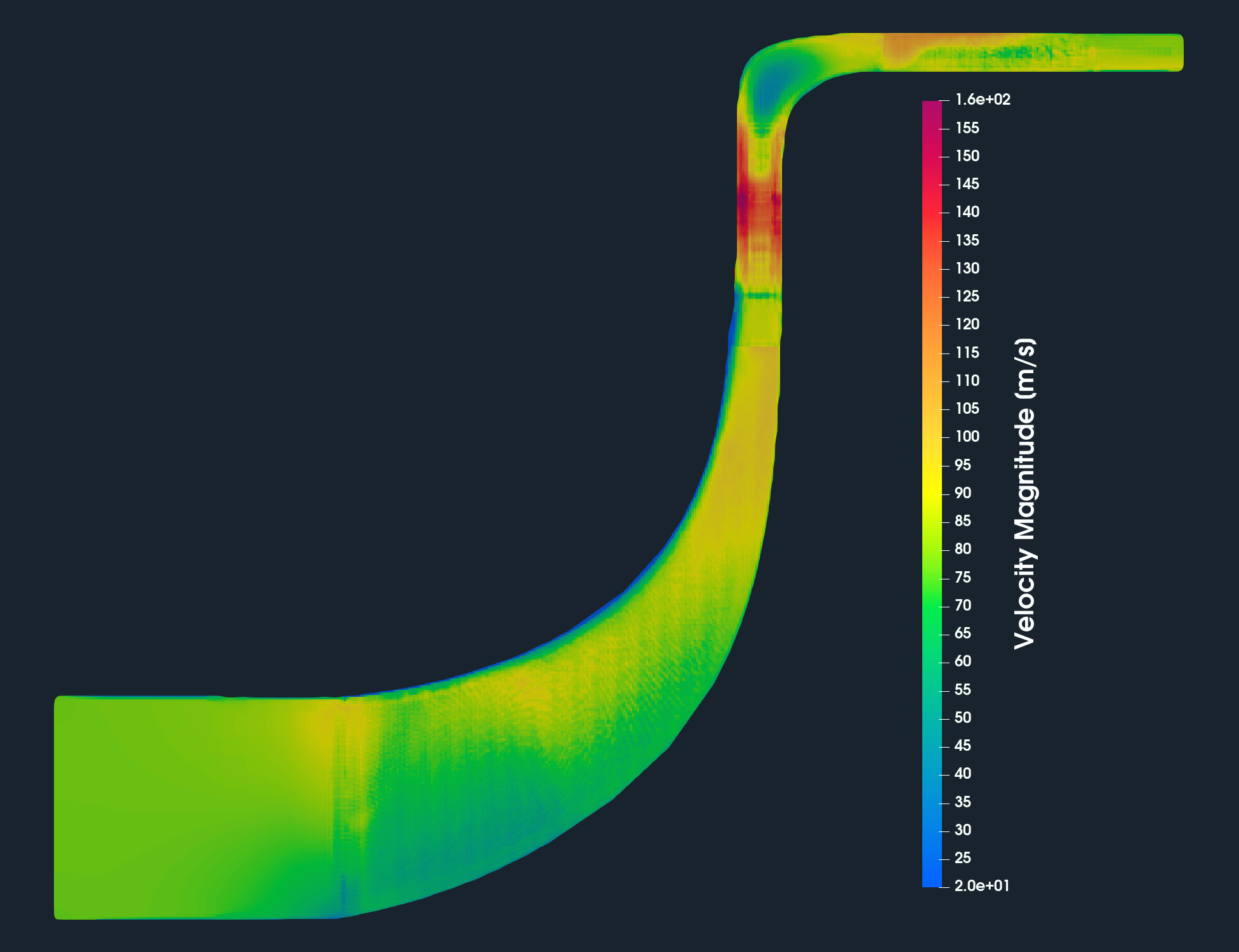
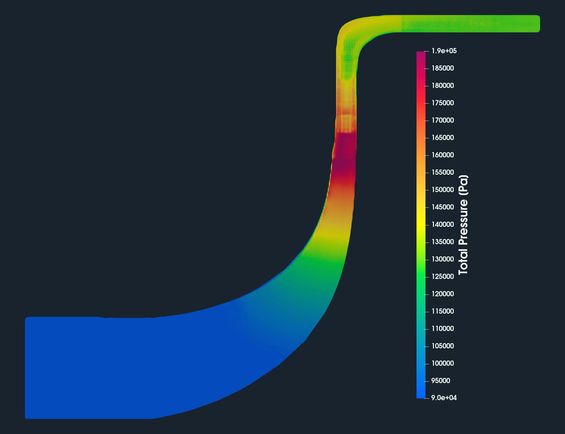
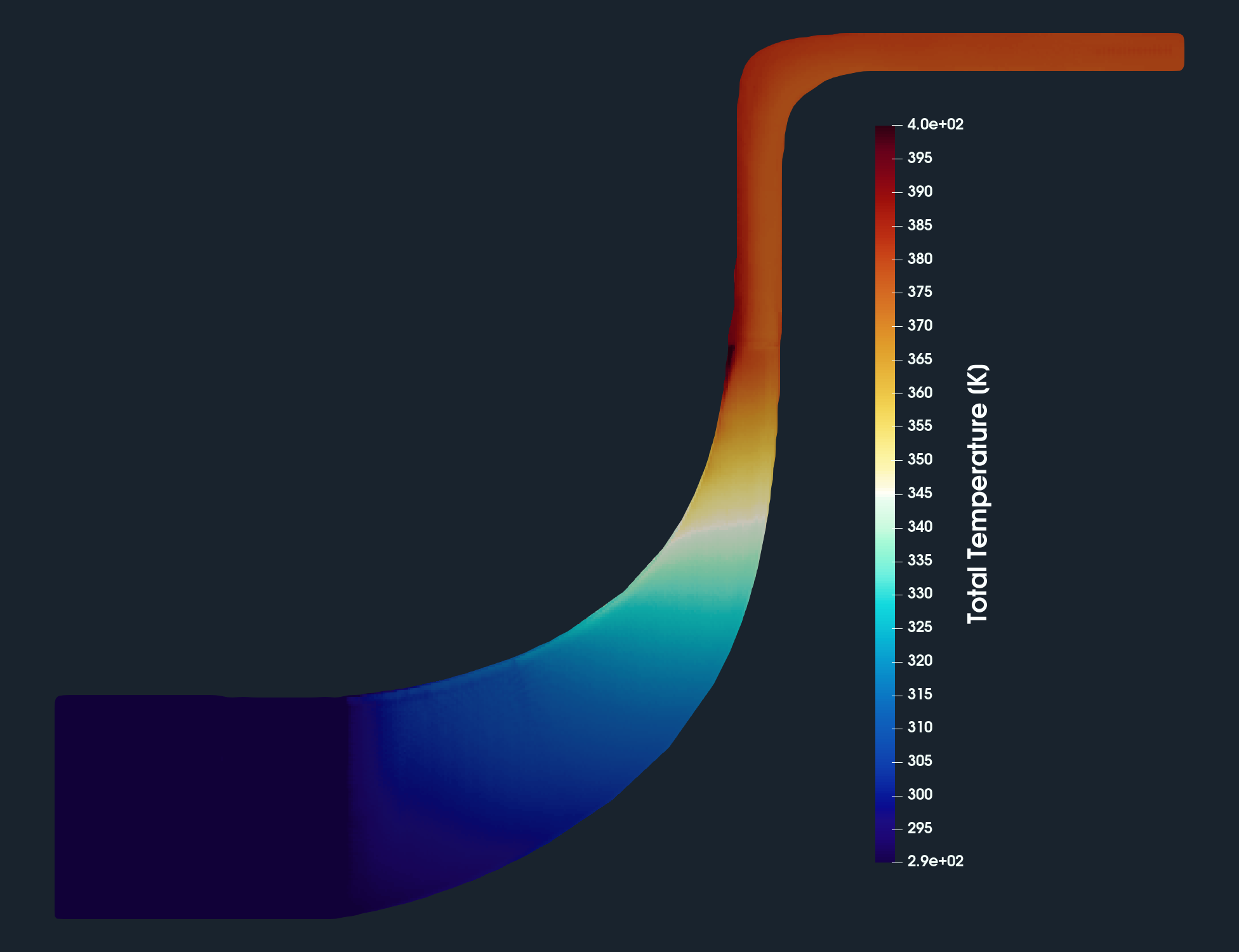
HECC Stage - Meridional View
For engineers who deal with rotating machinery, it is typically important to see the results, for example, total pressure, temperature, or velocity, circumferentially averaged and projected on the meridian plane. This visualization method is called the Meridional Average. This meridional average projection avoids for example the impeller blades and shows how the pressure (energy) or velocity is distributed along the meridian (a 2D interpretation of flow through the machine). The meridional average provides valuable information about pressure discharge distribution. Technically, the volume field data are circumferentially averaged and interpolated on the meridional plane of a certain resolution.
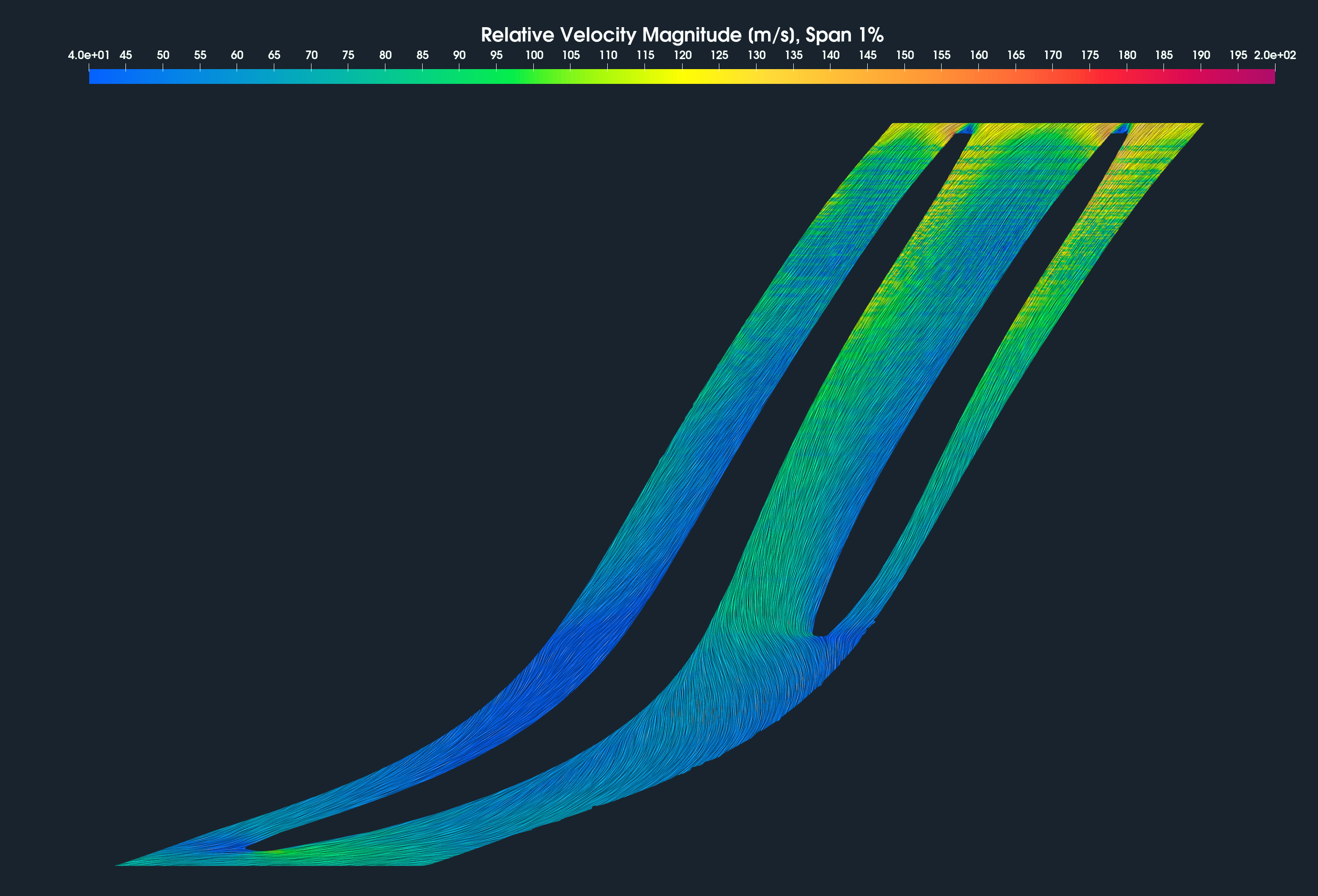
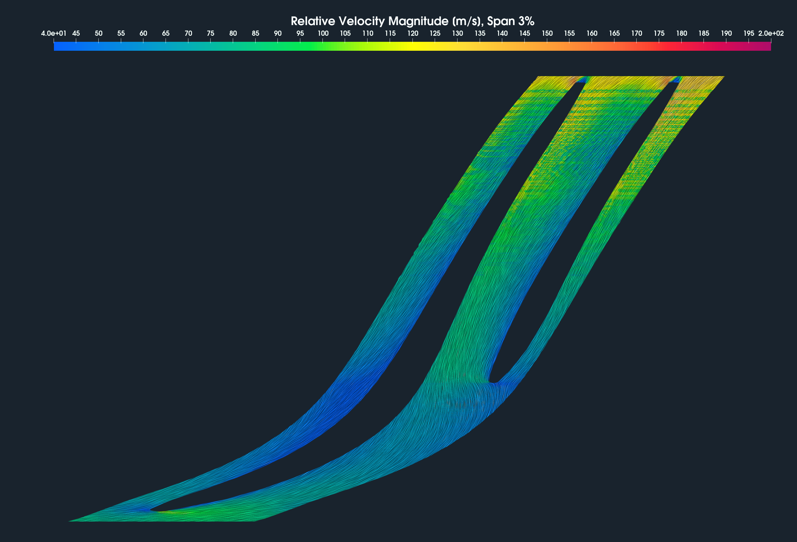
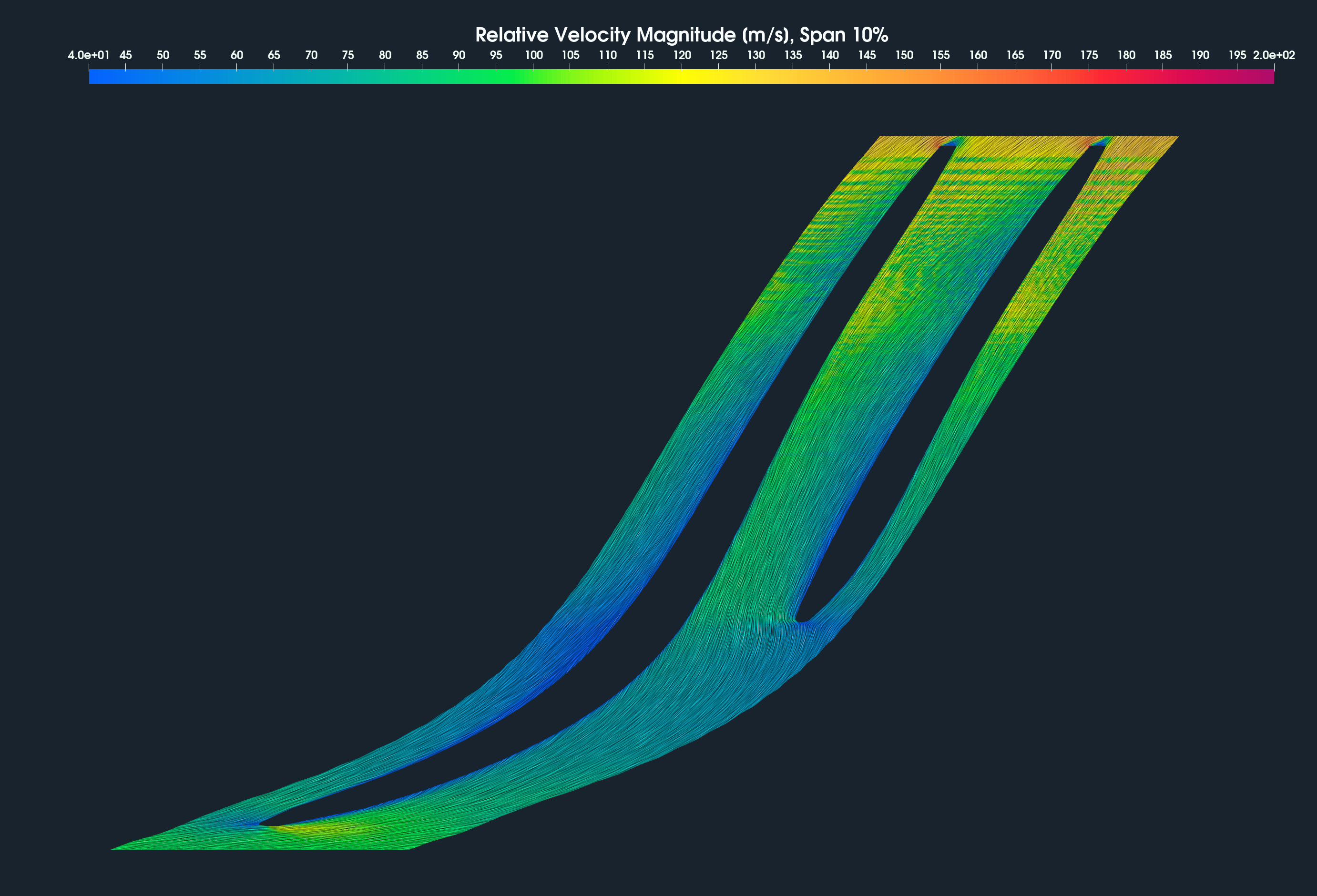
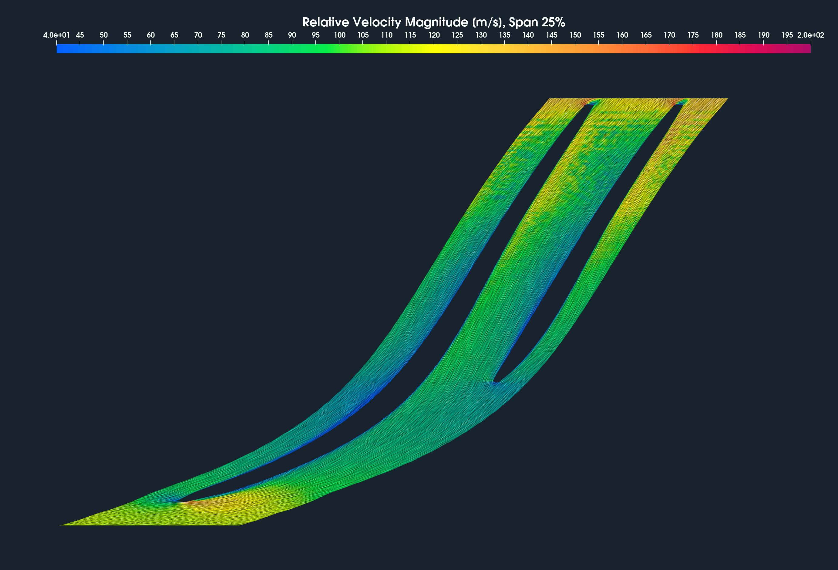
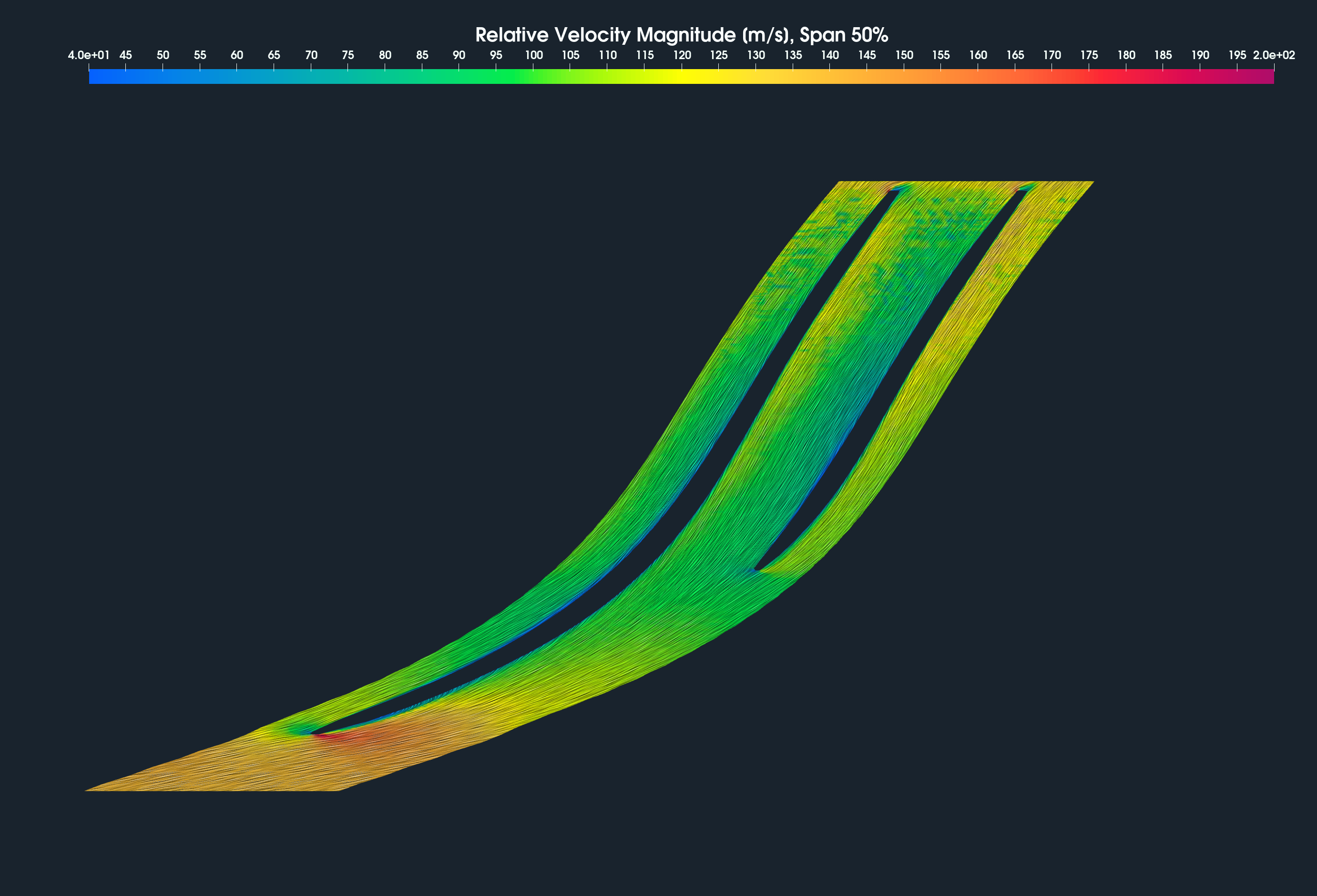
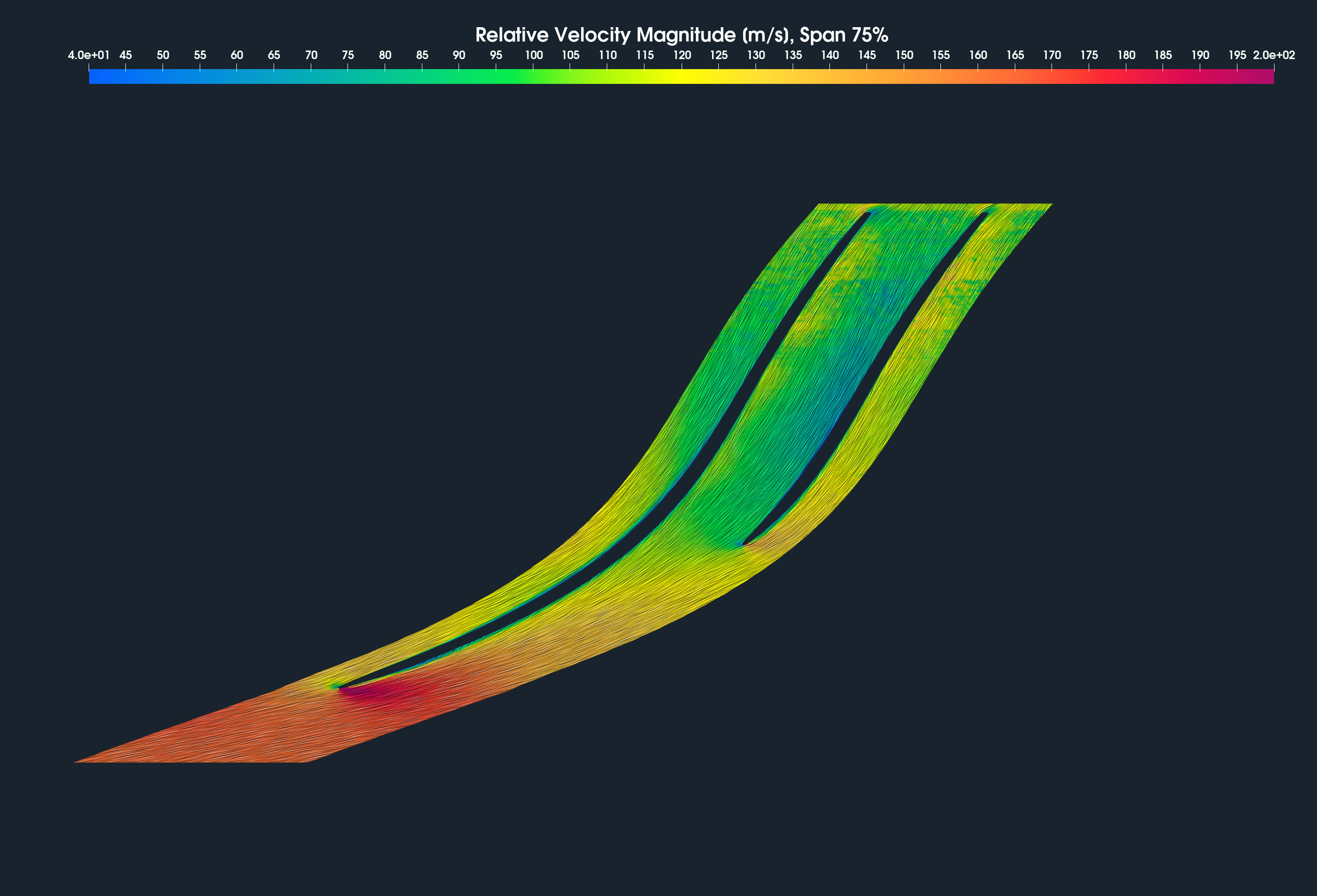
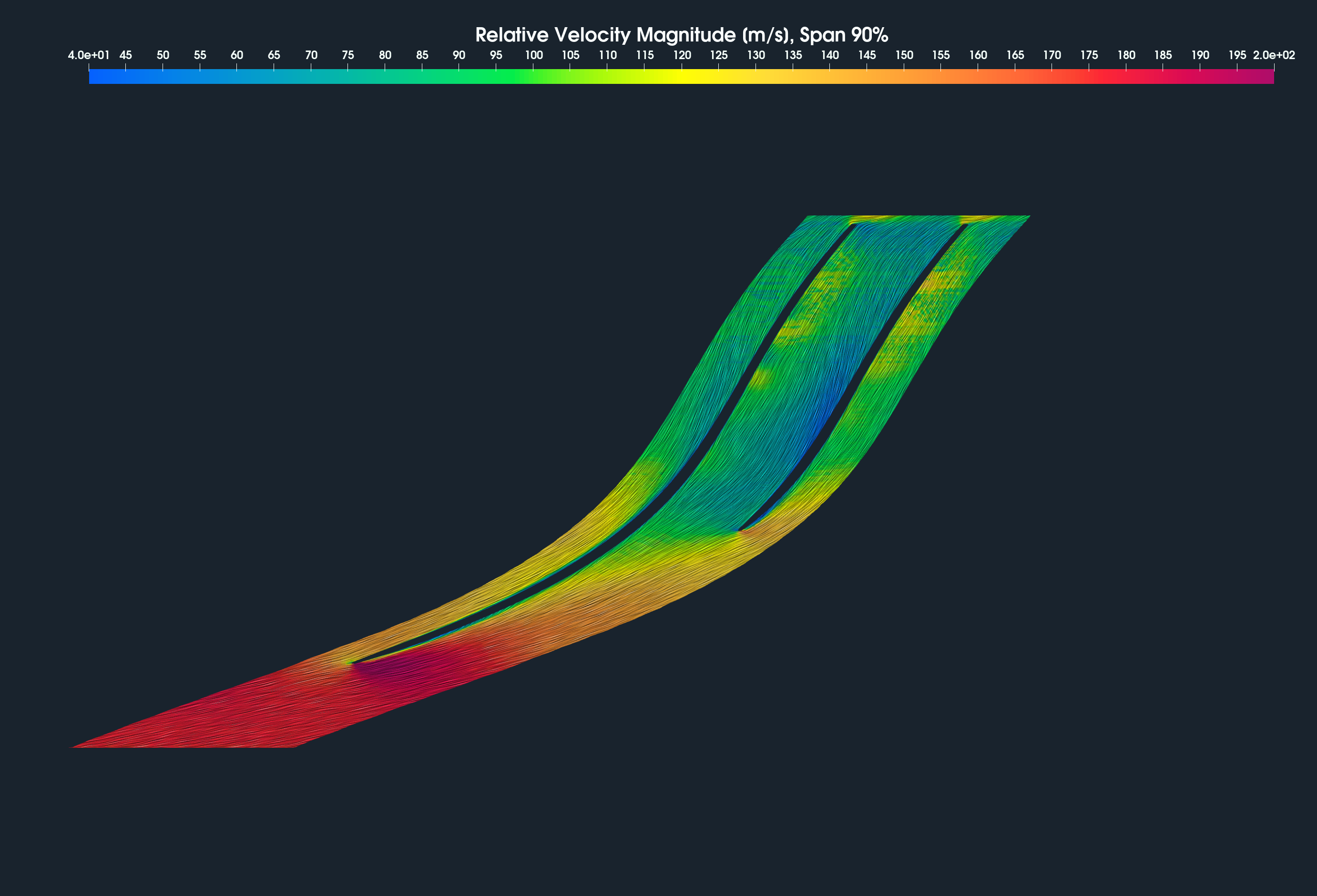
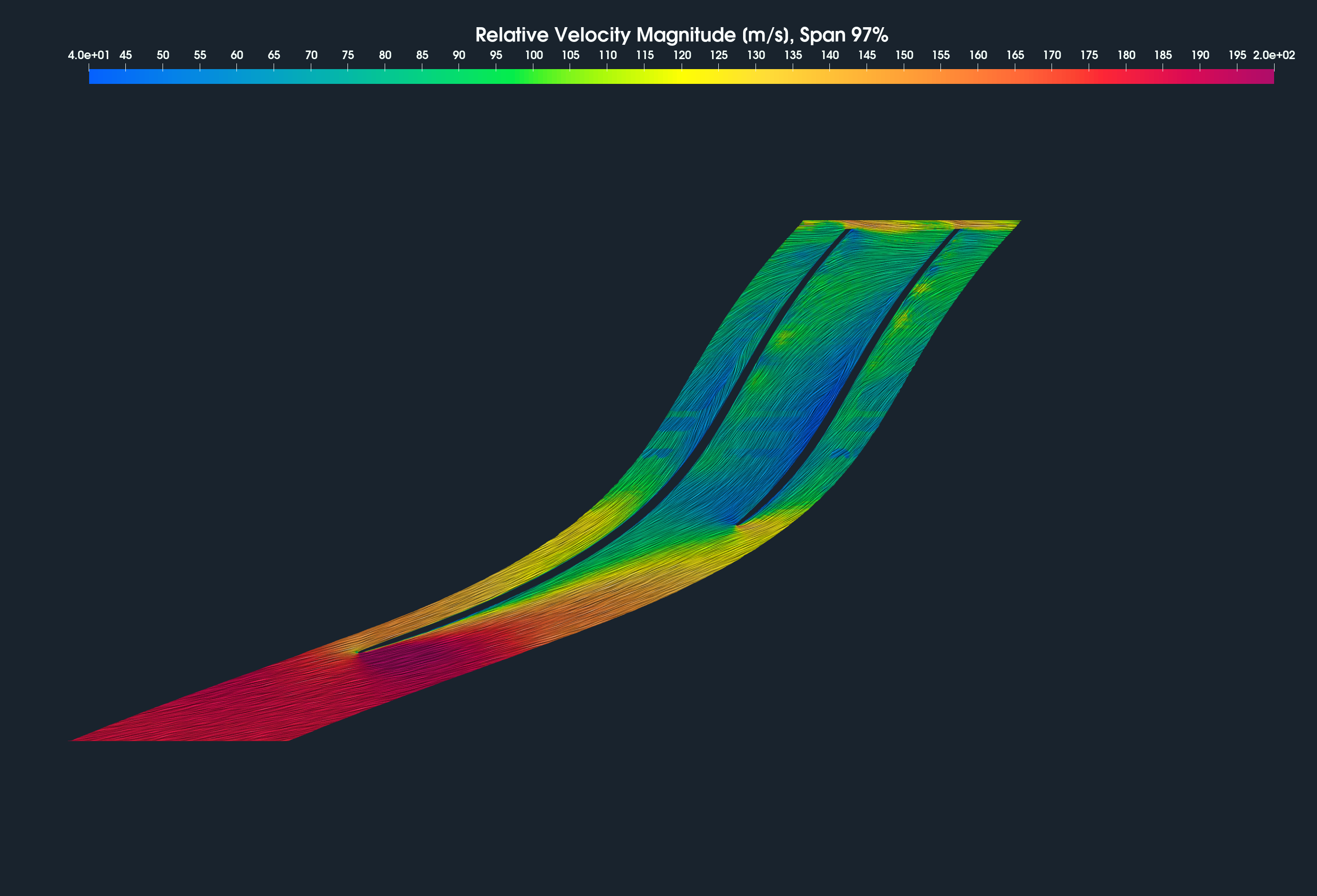
HECC Stage - Blade to Blade View
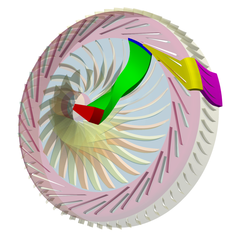
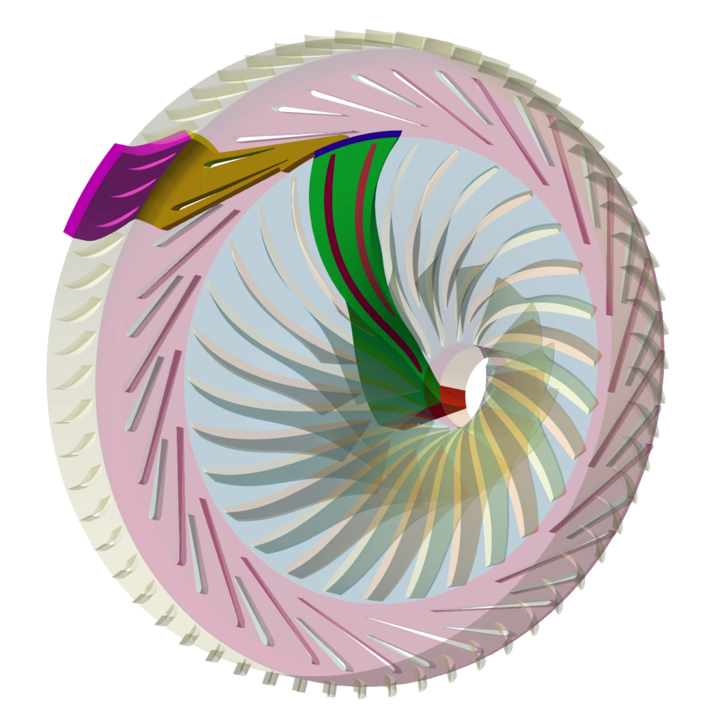
Blade to blade view is a special visualization method that transforms (unwraps) the rotational object (and its corresponding volume fields) into the dimensionless hexahedron of edges 2phi x 1 x 1. The blade-to-blade view offers a unique perspective that allows an inspection of the flow between the blades on any plane at a fixed relative distance between hub and shroud surfaces. This visualization method helps the engineers to check the angles at the leading and trailing edges at specific levels between hub and shroud.
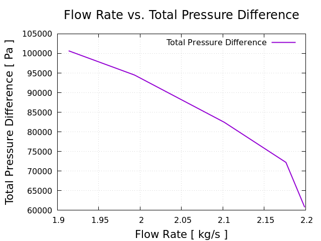
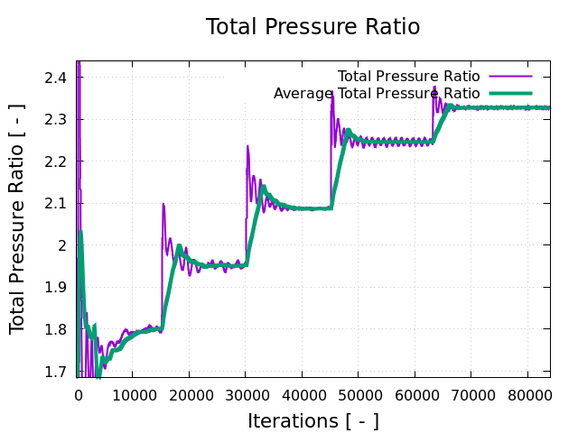
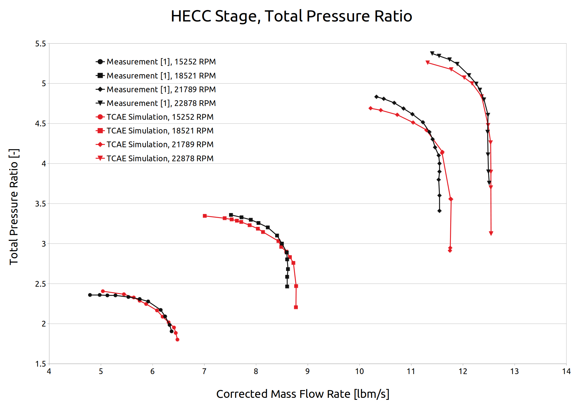
HECC Stage - Benchmark Results - Pressure Ratio
The HECC stage benchmark was extensively measured [1] in NASA laboratories to provide experimental data. The measurement is described in detail in [1]. We have chosen the four most important speed lines 15252, 18521, 21789, and 22878 RPM corresponding to 70%, 85%, 100%, and 105% of design speed. The following characteristics show the total pressure ratio and comparison between simulation and measurement.
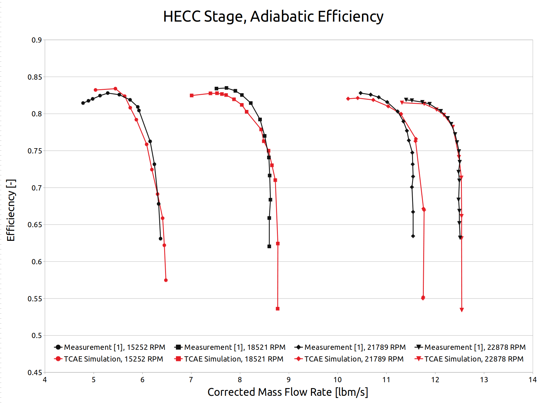
HECC Stage - Benchmark Results - Efficiency
The HECC stage benchmark was extensively measured [1] in NASA laboratories to provide experimental data. The measurement is described in detail in [1]. We have chosen the four most important speed lines 15252, 18521, 21789, and 22878 RPM corresponding to 70%, 85%, 100%, and 105% of design speed. The following characteristics show the compressor’s adiabatic efficiency and comparison between simulation and measurement.
Conclusion
- It has been shown how to make a comprehensive CFD & FEA analysis including FSI of the HECC Stage in a single automated workflow.
- The TCAE results were successfully compared to the measurement data.
- There was no special tweaking used in the CFD simulation at all.
- There remains a lot of space for tuning the CFD methodology, especially for the mesh resolution, turbulence modeling, and numerical schemes.
- TCAE showed to be a very effective tool for CFD, FEA, and FSI engineering simulations for all rotating machinery in general.
- This benchmark study was intentionally written in short not to overwhelm its readers with too many details.
- The original intention was to show the modern simulation workflow and its potential.
- The benchmark details are listed in the references below [1] [2] [3] [4] [5].
- All the technical details regarding CFD & FEA simulation are listed in the TCAE manual.
- The benchmark geometry and data are freely available for download on the CFDSUPPORT website https://www.cfdsupport.com.
- More information about TCAE can be found on the CFD SUPPORT website: https://www.cfdsupport.com/tcae.html
- Questions will be happily answered via email info@cfdsupport.com.
Acknowledgement
Special thanks of gratitude to the technical advisor Tony Jones who gave CFDSUPPORT the idea to do this wonderful project and also helped do a lot of research and helped to discover so many new things about compressor design & simulation.
References
[1] Medic, G., Sharma, O.P., Jongwook, J. at al. (2014) High Efficiency Centrifugal Compressor for Rotorcraft Applications, NASA/CR—2014-218114/REV1
[2] Braunscheidel, Edward & Welch, Gerard & Skoch, Gary & Medic, Gorazd & Sharma, Om. (2014). Aerodynamic Performance of a High Efficiency Centrifugal Compressor at the Stage and Subcomponent Level. 10.2514/6.2014-3632.
[3] TCAE Training
[4] TCAE Manual
[5] TCAE Webinars
Download TCAE Tutorial - HECC Stage Benchmark
File name: HECC-stage-benchmark-TCAE-Tutorial-21.09.zip
File size: 32 MB
Tutorial Features: CFD, FEA, FSI, TCAE, TMESH, TCFD, TFEA, SIMULATION, COMPRESSOR, RADIAL COMPRESSOR, CENTRIFUGAL COMPRESSOR, TURBOMACHINERY, COMPRESSIBLE FLOW, DEFORMATION, DISPLACEMENT, STRESS, MODAL ANALYSIS, COMPRESSIBLE, RANS, STEADY-STATE, AUTOMATION, WORKFLOW, RADIAL FLOW, SEGMENT, SNAPPYHEXMESH, NETGEN, 5 COMPONENTS, RPM=2178900, R=11mm