The Rushton impeller is a classic radial-flow mixer widely used in chemical and process engineering. Despite its simple geometry, it produces highly complex, unsteady flow structures—especially when multiphase effects are involved.
PDF Report
CFD Simulation Report
Geometry Description
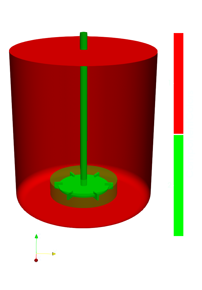
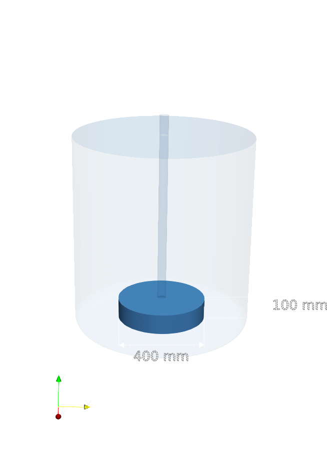
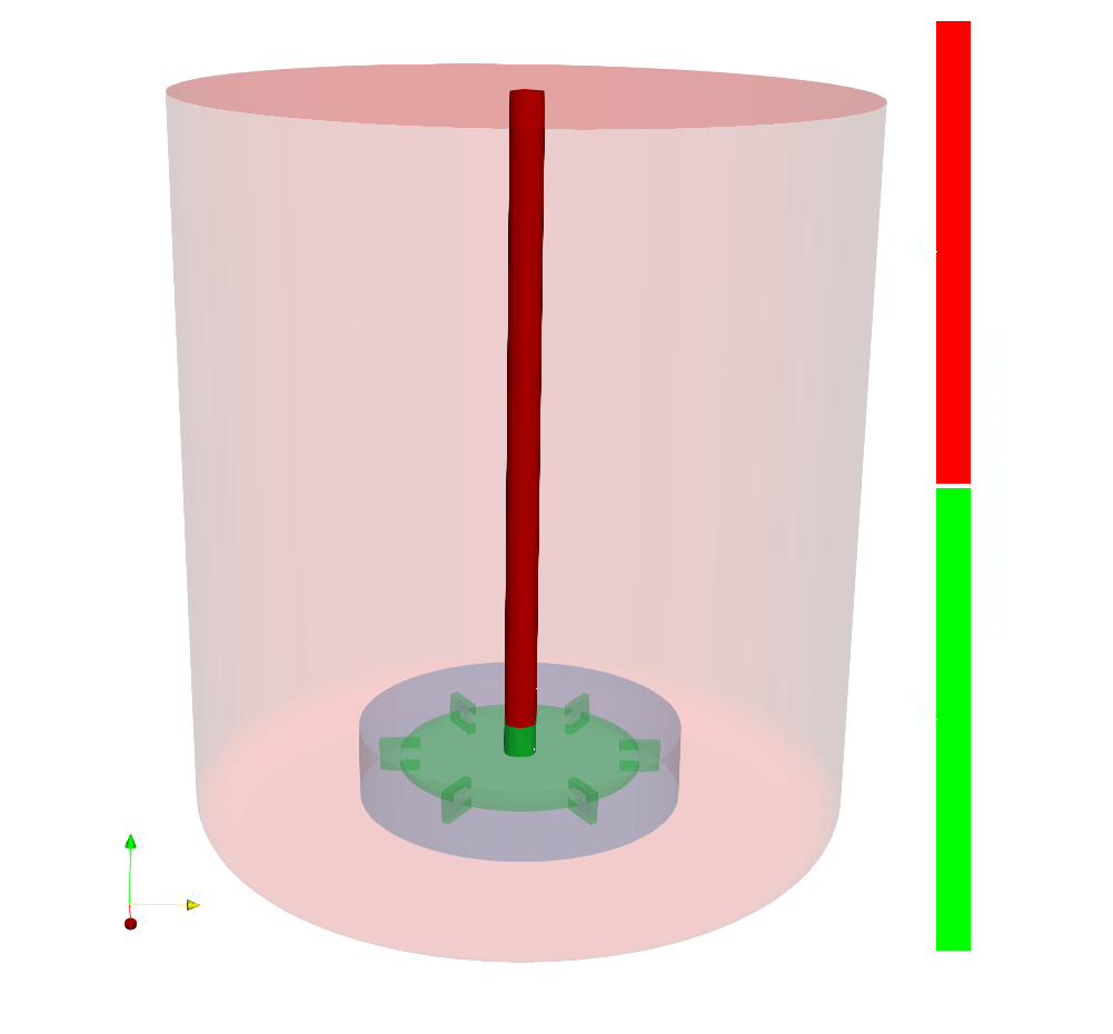
The geometry represents a standard stirred tank equipped with a Rushton turbine, whose design is based on a flat horizontal disk, with flat, vertically mounted blades.
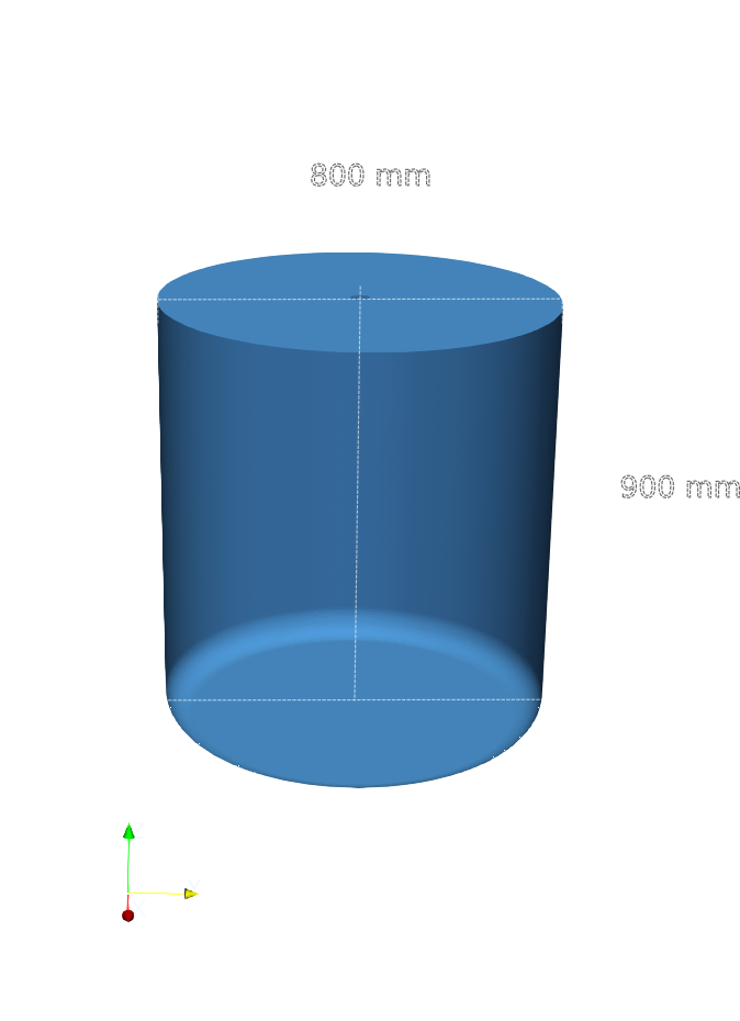
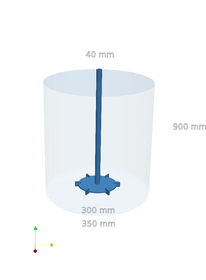
The mixing vessel has a inner diameter 800 mm and a total height 900 mm. While the main body of the vessel is cylindrical, the bottom is not flat. Instead, it features a smoothly rounded bottom section. Furthermore, no baffles are included in the current configuration.
The Rushton impeller is centrally mounted on a vertical shaft. The impeller consists of a flat horizontal disk fitted with six flat, vertically oriented blades, evenly spaced around the disk circumference. The impeller diameter is 350 mm and each blade has a height of 40 mm, and a width of 50 mm.
During operation, the impeller rotates at a constant speed of 400 RPM. Due to the absence of baffles, the flow is expected to exhibit significant swirling motion.
CFD Preprocessing
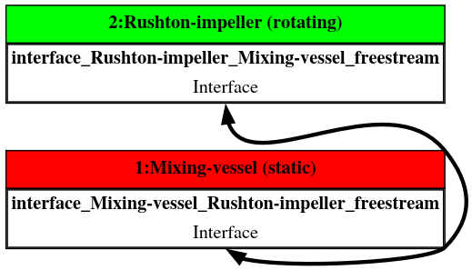
The computational domain is divided into two subdomains: a stationary mixing vessel and a rotating Rushton impeller region.
During preprocessing, the geometry is organized into two components.
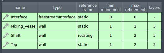
Component 1 represents the mixing vessel region and includes the cylindrical vessel, the top lid and the shaft.
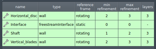
Component 2 represents the Rushton impeller and includes the shaft, the horizontal disc, and six equally spaced vertical blades.
Additionally each component includes an interface.
Mixing vessel
Rushton impeller
Interface
CFD Meshing
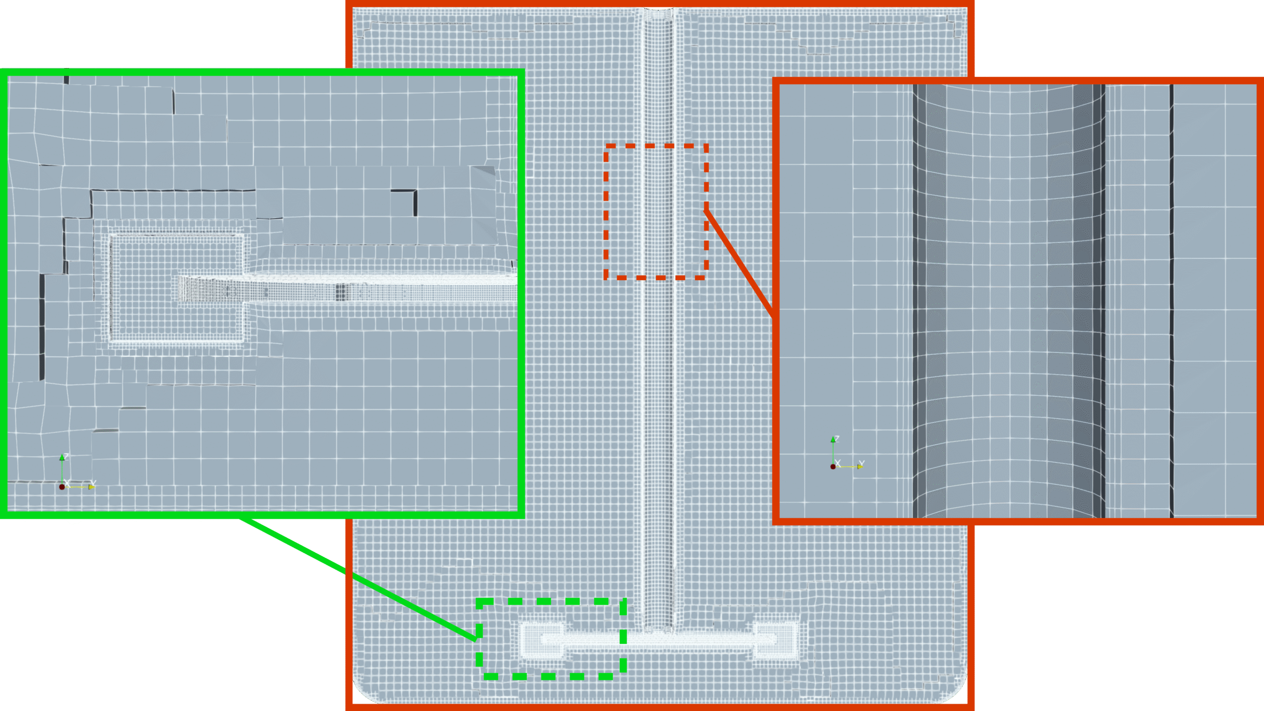
For each component, the computational mesh can be either generated in automated software module TMESH, using the snappyHexMesh open-source mesh generation utility or imported from an external source. Both approaches can be combined within the same simulation setup, allowing maximum freedom in how the mesh is constructed.
In this test case, the computational mesh is generated within the OpenFOAM framework using snappyHexMesh, following a approach based on a structured background mesh combined with local refinements and boundary layer inflation. A Cartesian background mesh is first created using blockMesh, with a uniform base cell size of 0.01 m throughout the computational domain. This background mesh serves as the starting point for all subsequent refinement operations.
Although snappyHexMesh was used in this case, it is not required by the TCAE environment—any external mesh may be loaded directly in supported formats such as MSH, CGNS, or OpenFOAM format.
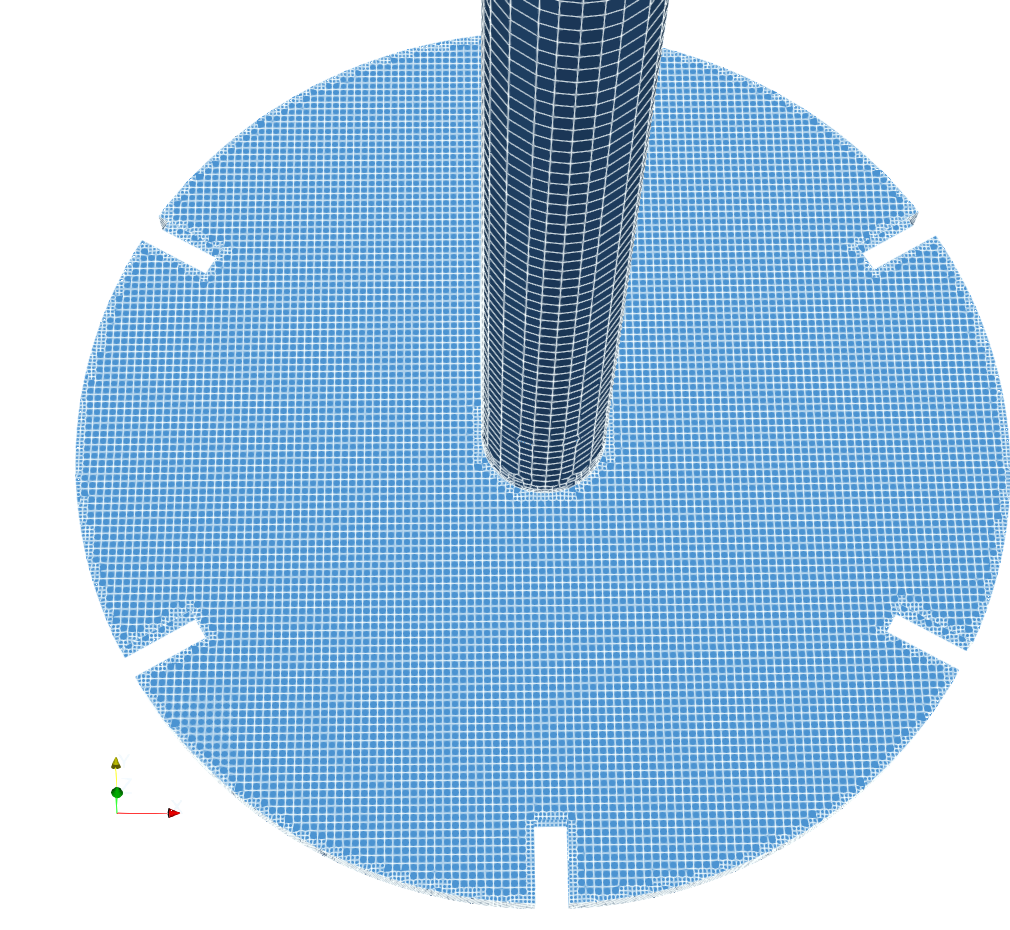
Component 1 - Mixing-vessel
Component 2 - Rushton-impeller
The shaft is present in both components, as it spans in both components. During meshing, the shaft geometry is split by the interface surface, which defines the boundary between the two regions. As a result, only the portion of the shaft that belongs to each respective region is retained in that component. As highlighted in the adjacent visualization, the shaft is split by the interface and appears in both components.
Both components include a interface surface of type freestreamInterface (See Patches Table in TCAE manual).
Boundary layers are applied on wall surfaces to resolve near-wall flow effects.
It should be noted that this configuration is highly sensitive to mesh resolution.
CFD Simulation Setup
The CFD simulation is performed using the TCFD module, part of the TCAE simulation framework. The entire CFD simulation setup and execution are carried out through the TCFD GUI integrated within ParaView. TCFD uses OpenFOAM open-source application.
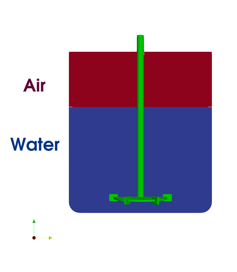
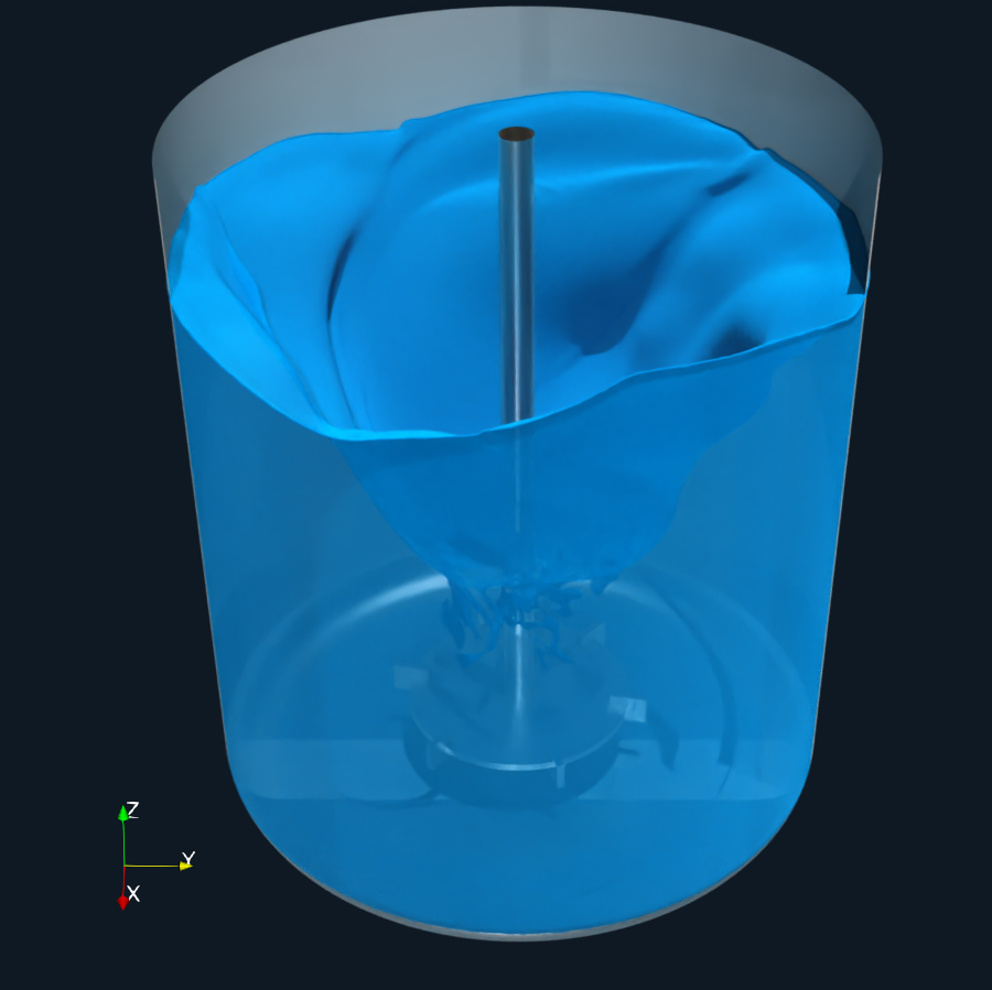
The simulation is performed as a transient, incompressible flow using a two-phase Volume of Fluid (VoF) approach to model water and air. The water phase is defined as the primary phase, while air is treated as the secondary phase with its own fluid properties.
The primary phase (water) is specified under Physics: Fluid Properties. The secondary phase (air) is activated by enabling Multiphysics: Multiphase VoF, where its fluid properties (name, density, viscosity) are defined. In addition, surface tension between the two phases is specified within the VoF settings.
Initial phase distribution is prescribed in Boundary Conditions: Initial Conditions, where the second-phase volume is defined. By default, the entire domain is initialized with the first phase, and the second phase is then assigned to selected regions based on the specified second-phase volume. In this case, the second phase is initialized using a box-shaped volume, although other shapes such as sphere or cylinder can also be used.
The VoF method belongs to the Eulerian class of modeling approach and is based on the idea of using a fraction function alpha, which indicates the presence of phase within each control volume. A value equal to one corresponds to a cell fully occupied by selected phase, while value equal to zero indicates the other phase. Intermediate values represent cells containing the phase interface.
For VoF method, it is crucial too use a sufficiently fine mesh in order to accurately resolve the phase interface. Alternatively, dynamic mesh refinement based on the volume fraction alpha can be employed to locally refine the mesh in regions containing the phase interface.
TCAE Simulation type: propeller
Number of components: 2 [-]
Speedlines: 1 [-]
Simulation points: 1 [-]
Wall roughness: none
Turbulence: k-ω-SST
Wall treatment: Wall functions
Time management: Transient
Time step: constant, 0.5°
Dynamic Mesh
Physical run-time: 5 s
Physical model: Incompressible
Gravity
Multiphase VoF
Surface tension: σ=0.07
Primary phase: Water
density: ρ = 998 kg/m3
viscosity: ν = 1.002 e-6 m2/s
Secondary phase: Air
density: ρ = 1.2 kg/m3
viscosity: ν = 1.5 e-5 m2/s
Turbulence is modeled using the k–ω SST model, with standard wall functions applied at all walls. All solid boundaries are treated as no-slip walls. Gravity effects are included.
The simulation employs a constant time step, defined based on the impeller rotation, corresponding to a 5-degree angular increment per time step. The case is configured to run for a physical time of 5 s.
The setup includes one speedline and one simulation point, and a dynamic mesh approach is employed to account for the impeller rotation.
Pressure–velocity coupling is handled using the PIMPLE algorithm.