This study presents a complex step-by-step analysis of a Francis turbine from its preprocessing to an advanced CFD & FEA simulation, including FSI and modal analysis. The simulation software used for this analysis is TCAE – a comprehensive simulation environment based on open-source. This particular Francis hydro turbine is a CFD benchmark validation of a real existing turbine. This project was made together with Hidroenergia, a hydro turbine manufacturing company. This project is unique because the real existing hydropower turbine was physically measured and the measurement data were compared with the data from the CFD simulation by TCAE. The main goal of this benchmark is to compare the turbine efficiency and power of the TCAE simulation results with the real experimental measurement data measured by Hidroenergia.
Another goal of this study is to show in detail how to make a comprehensive CFD & FEA + FSI analysis of the Francis turbine characteristics: efficiency, head, torque, power, pressure, cavitation properties, material stress of the runner, material displacement of the runner, modal analysis of the runner, and many more.
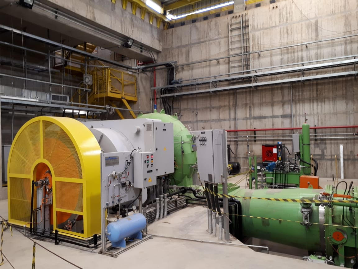
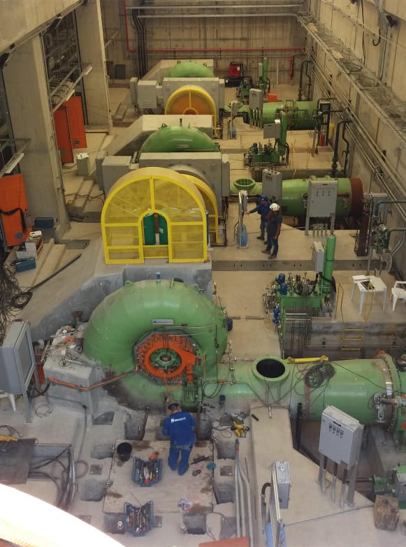
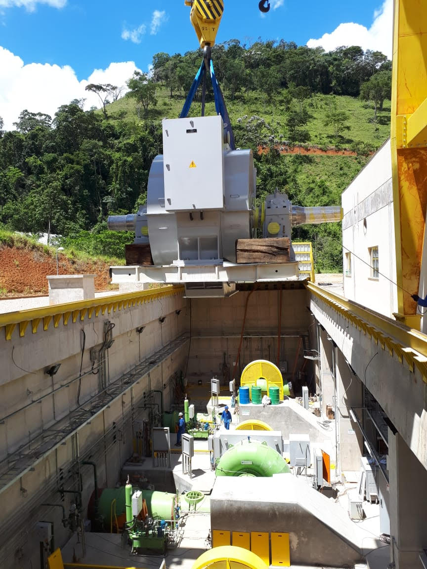
Francis Hydro Turbine - HPP FORTUNA II
Francis turbines are the most common water turbine in use today. This particular Francis turbine which was researched in this benchmark is called HPP FORTUNA II, and it was installed in Minas Gerais, Brazil. Hydropower plant has three Francis turbine units, the images on this page show the installation process. The Francis turbine is an inward flow reaction turbine that combines radial and axial flow concepts. Reaction turbine, a category of the turbine in which the working fluid comes to the turbine under immense pressure and the energy is extracted by the turbine blades from the working fluid. A part of the energy is given up by the fluid because of pressure changes occurring in the blades of the turbine, quantified by the expression of the degree of reaction, while the remaining part of the energy is extracted by the volute casing of the turbine. At the exit, water acts on the spinning cup-shaped runner features, leaving at low velocity and low swirl with very little kinetic or potential energy left. The turbine’s exit tube is shaped to help decelerate the water flow and recover the pressure.
A Francis turbine consists of the following main parts: Spiral casing: The spiral casing around the runner of the turbine is known as the volute casing or scroll case. Throughout its length, it has numerous openings at regular intervals to allow the working fluid to impinge on the blades of the runner. These openings convert the pressure energy of the fluid into kinetic energy just before the fluid impinges on the blades. This maintains a constant velocity despite the fact that numerous openings have been provided for the fluid to enter the blades, as the cross-sectional area of this casing decreases uniformly along the circumference. Guide and stay vanes: The primary function of the guide and stay vanes is to convert the pressure energy of the fluid into kinetic energy. It also serves to direct the flow at design angles to the runner blades.
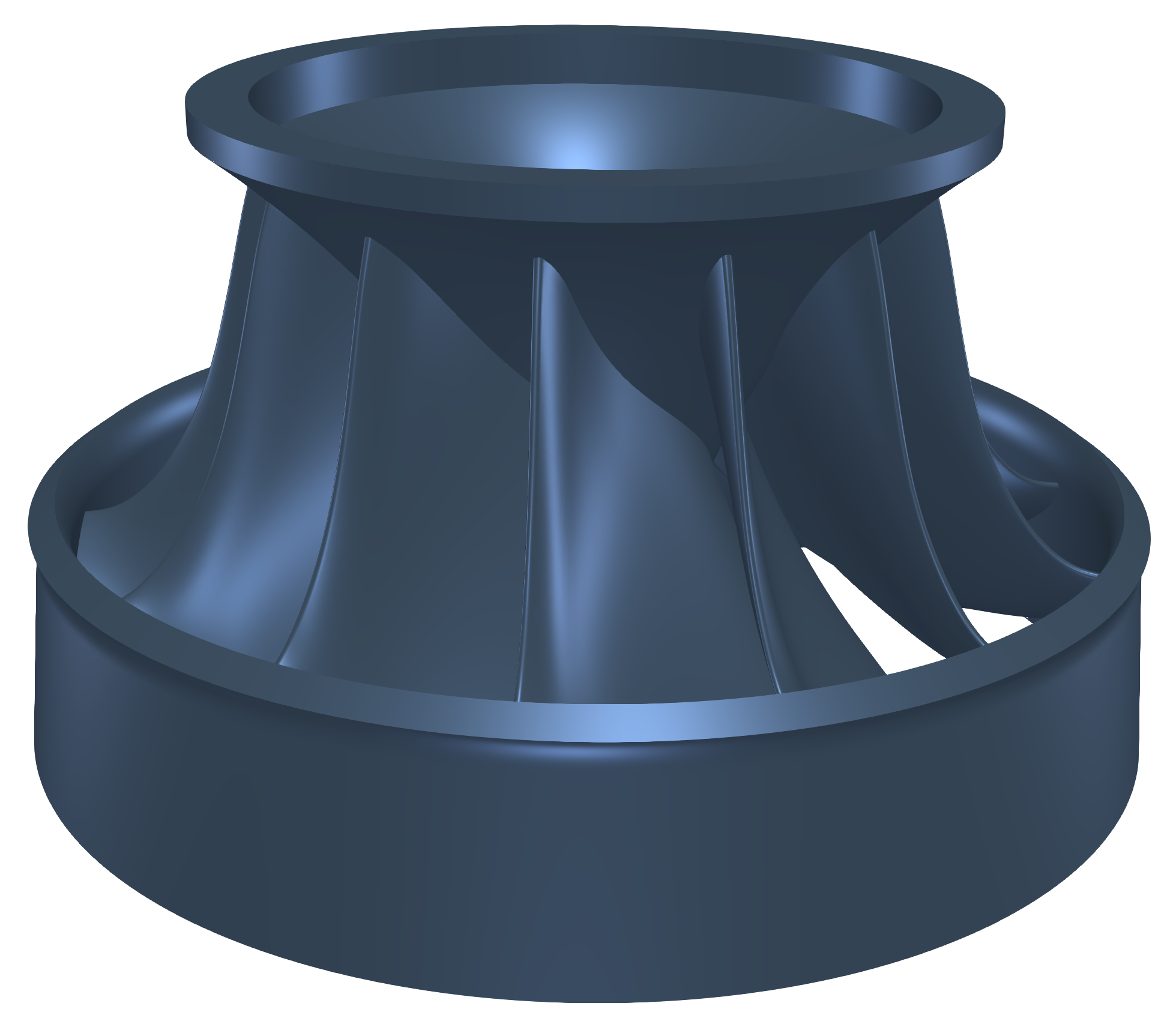
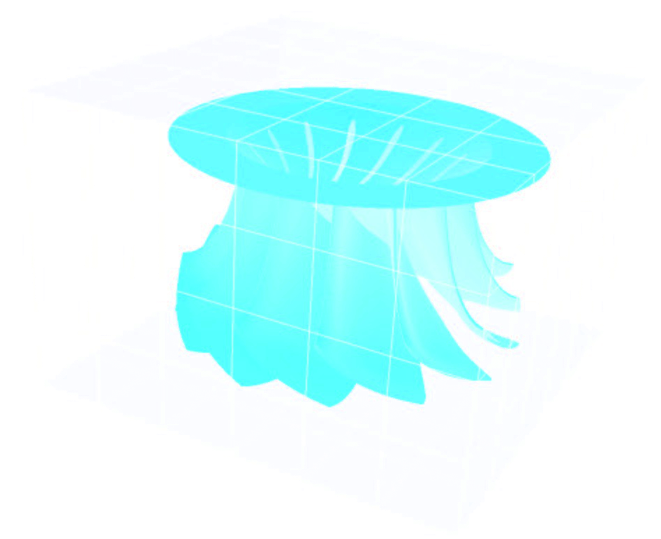
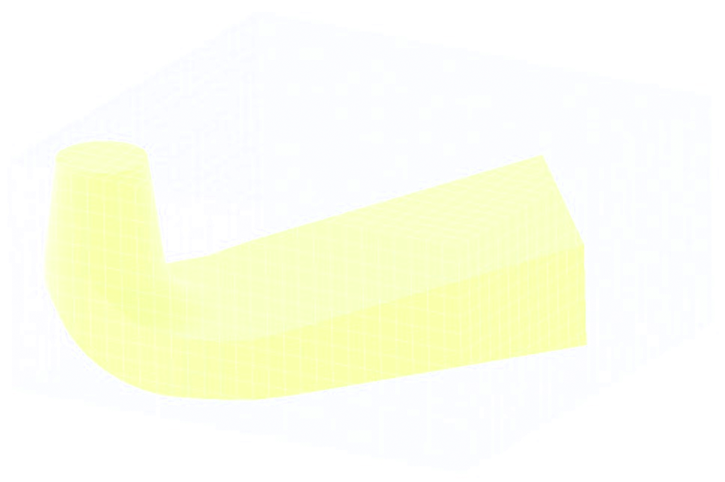
Runner blades (Impeller): Runner blades are the heart of any turbine. These are the centers where the fluid strikes and the tangential force of the impact causes the shaft of the turbine to rotate, producing torque. Close attention to the design of blade angles at inlet and outlet is necessary, as these are major parameters affecting power production. Draft tube: The draft tube is a conduit that connects the runner exit to the tailrace where the water is discharged from the turbine. Its primary function is to reduce the velocity of discharged water to minimize the loss of kinetic energy at the outlet. This permits the turbine to be set above the tailwater without an appreciable drop of the available head.
Francis Turbine Benchmark - CFD Preprocessing
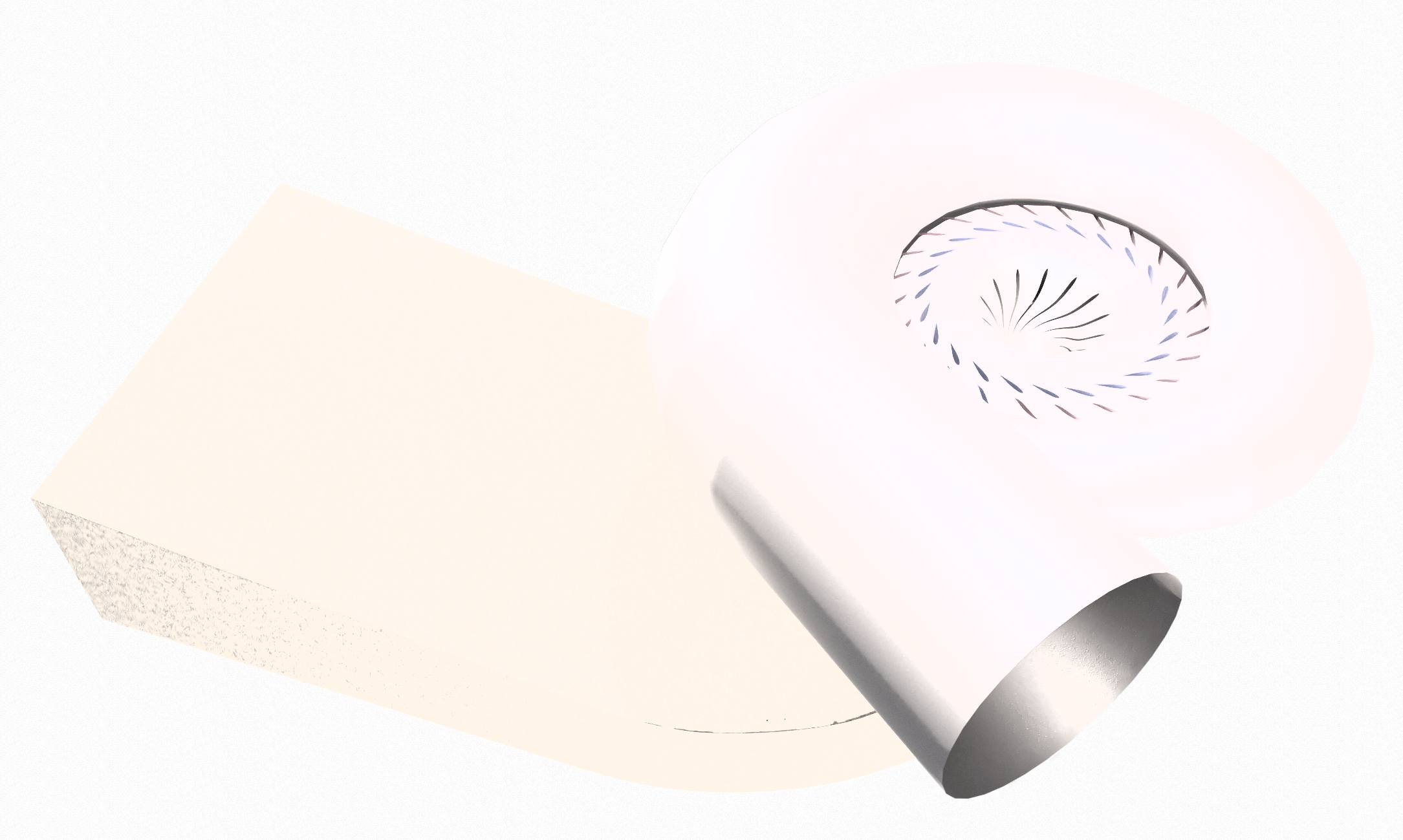
A typical input for a detailed simulation analysis is a watertight (wet) surface model in form of an STL surface. For CFD simulation, it is needed to have a closed watertight model (sometimes called waterproof model, or model negative, or wet surface) of the CAD model inner parts where the fluid flows. For FEA simulation, it is needed to have a closed surface model of the solid of the impeller (runner) in form of a single one closed STL surface. The CAD model of the Francis turbine was received in the STEP file format. Original STEP files are usually too complex for comprehensive CFD and FEA simulations, so certain preprocessing (cleaning) CAD work is generally required. While the original CAD model for this project was simplified and cleaned using Salome open-source software, any other standard CAD system can be used instead.
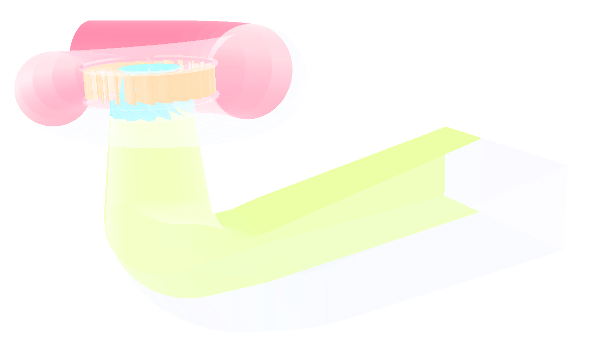
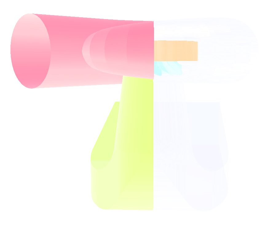
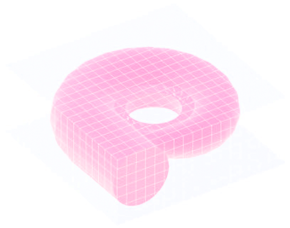
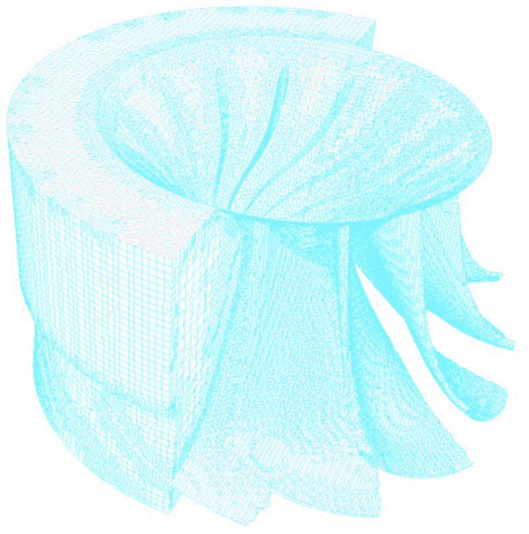
The principle is always the same: the surface model has to be created; all the tiny, irrelevant, and problematic model parts must be removed, and all the holes must be sealed up (watertight surface model is required). This Francis turbine CAD model is reasonably simple. The final surface model in the STL format is created as input for the meshing phase. This preprocessing phase of the workflow is extremely important because it determines the simulation potential and limits the CFD results. In this Francis turbine project, the CAD model was split into three logical parts: Spiral casing + Stay + Guide vanes, Impeller, and Draft tube. Each turbine part is watertight and includes an inlet interface, outlet interface, and corresponding walls (wall, blade, hub, shroud, stay vanes, guide blades). For each individual turbine, part has been created its own volume mesh, and during the simulation, the meshes are merged by the TCAE processor.
All the tiny, irrelevant, and problematic model parts must be removed, and all the holes must be sealed up. This Francis turbine CAD model is reasonably simple. The surface model in the STL format is created as input for the meshing phase. This preprocessing phase of the workflow is extremely important because it determines the simulation potential and limits the CFD results.
The surface model data in .stl file format together with physical inputs are loaded in TCFD. Other option would be loading an external mesh in OpenFOAM® mesh format, or loading an MSH mesh format (Fluent mesh format). This CFD methodology employs a multi component approach, which means the model is split into a certain number of regions. In TCFD each region can have its own mesh and individual meshes comunicate via interfaces.
Francis Turbine - FEA Preprocessing
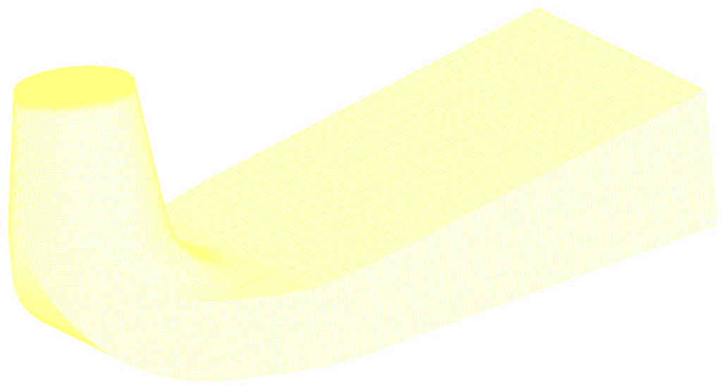
For the FEA analysis, the principle is very similar to CFD preprocessing. It is best to create a simple, single one, closed STL surface of the Francis turbine runner (impeller), for instance Francis-runner-solid.stl.
Now the model is ready for meshing with TMESH using NetGen open-source application.
IMPORTANT NOTICE
Both for CFD and FEA analysis, the surface model has to be clean. The principle is always the same: the watertight surface model has to be created; all the tiny, irrelevant, and problematic model parts must be removed, and all the holes must be sealed up (the watertight surface model is required). The preprocessing phase is an extremely important part of the workflow. It sets all the simulation potential and limits. It should never be underestimated. Mistakes or poor quality engineering in the preprocessing phase can be hardly compensated later in the simulation phase and postprocessing phase!!!
Francis Turbine - CFD Meshing
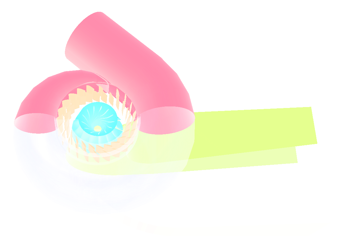
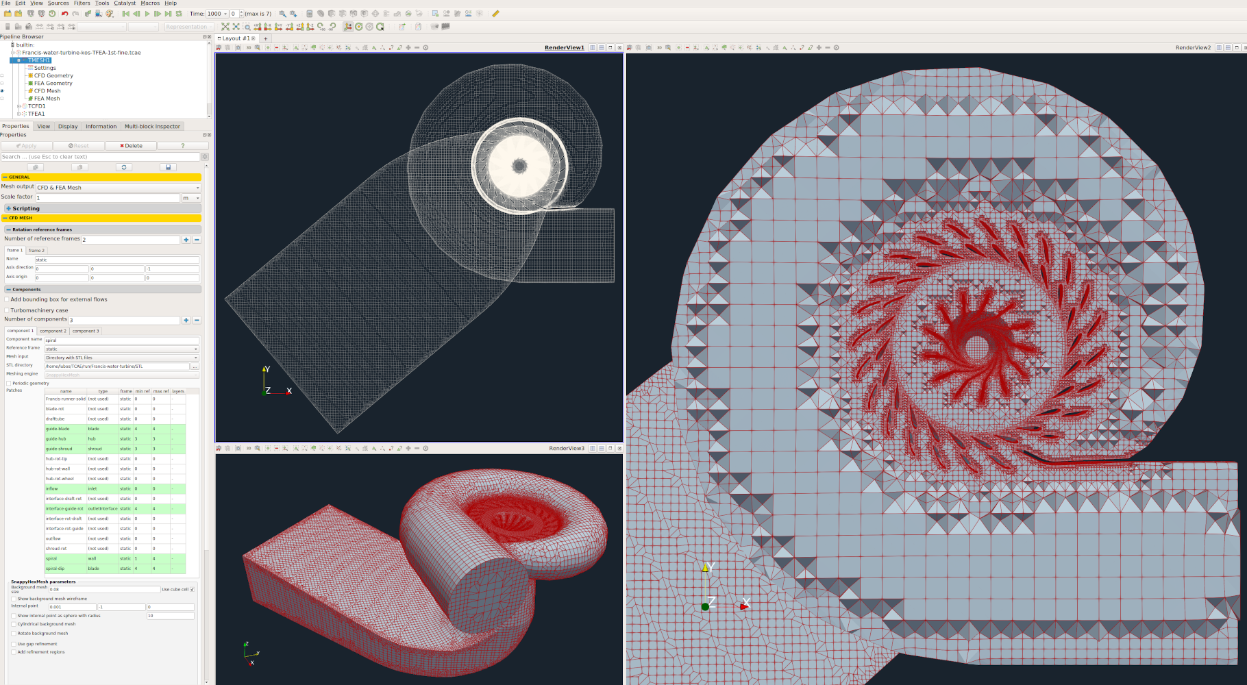
In this particular case, the Francis turbine model is split into three components. The Spiral (including the stay vanes and guide vanes), the Runner and the Draft tube. Each component has its own mesh. All the meshes are created automatically for each component within snappyHexMesh. Any number of model components is allowed, for example, a typical Francis turbine might have a five component alternative: Spiral, Stay, Guide, Runner, and Draft tube.
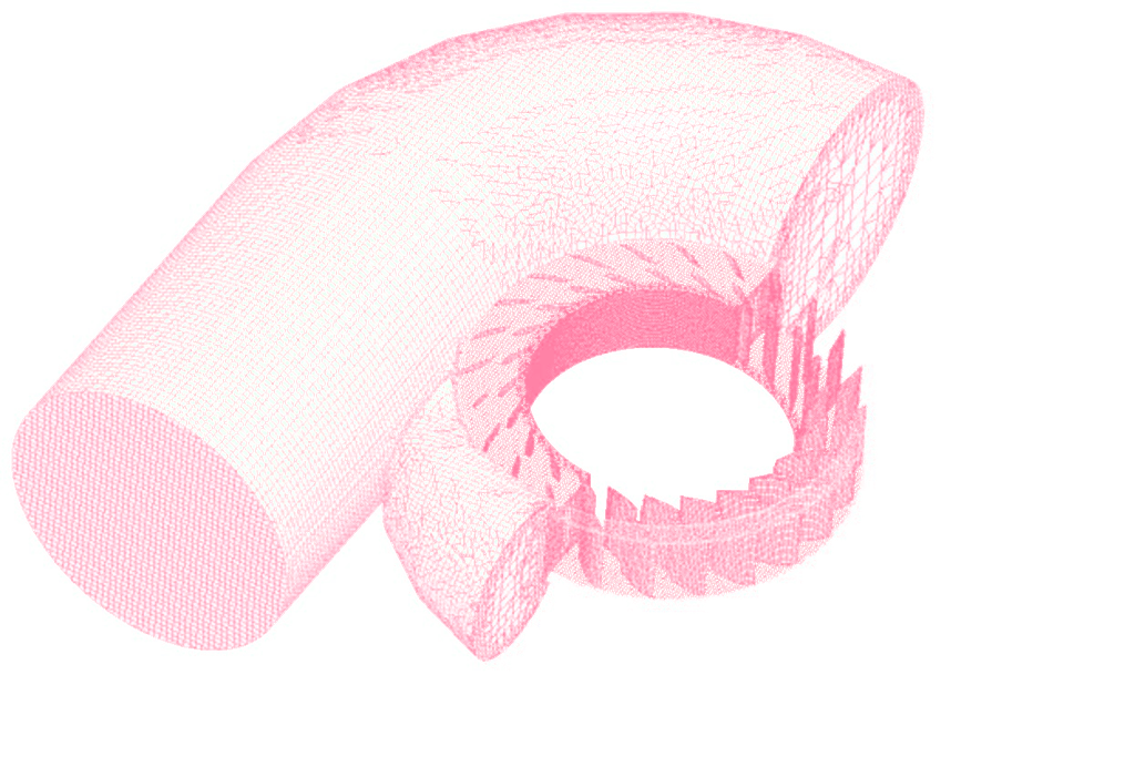
The computational mesh was created in an automated workflow using the snappyHexMesh application. For each turbine part (Spiral casing + Stay + Guide vanes, Runner, and Draft tube), a cartesian block mesh was used as an initial background mesh, that is further refined. The whole turbine model is 6237mm long, 3364mm high, and 3473mm wide. Basic mesh cell size is a cube of about 100mm edge. The mesh is gradually refined to the wall.
The mesh refinement levels can be easily changed, to obtain the coarser or finer mesh, to better handle the mesh size. Inflation layers can be easily handled. The final mesh used for the benchmark had in total 4,937,072 cells and consisted mostly of hexahedrons. (Spiral casing – 268751 , Stay+Guide vanes – 3256434, Impeller – 1253858, and Draft tube – 158029). The snappyHexMesh is not a compulsory meshing tool for TCAE at all. In case of need, any other external mesh can be loaded in TCAE directly in MSH, CGNS, or OpenFOAM format.
For each model component, a cartesian block mesh is created (box around the model), as an initial background mesh, that is further refined along with the simulated object. Basic mesh cell size is a cube defined with the keyword “background mesh size”. The mesh is gradually refined to the model wall. The mesh refinement levels can be easily changed, to obtain the coarser or finer mesh, to better handle the mesh size. Inflation layers can be easily handled if needed. For more details, see the TCAE documentation.
Francis Turbine - FEA Meshing
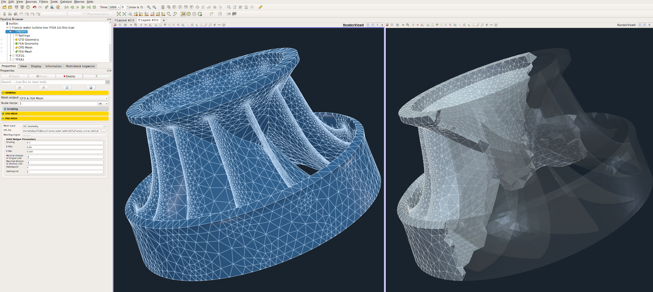
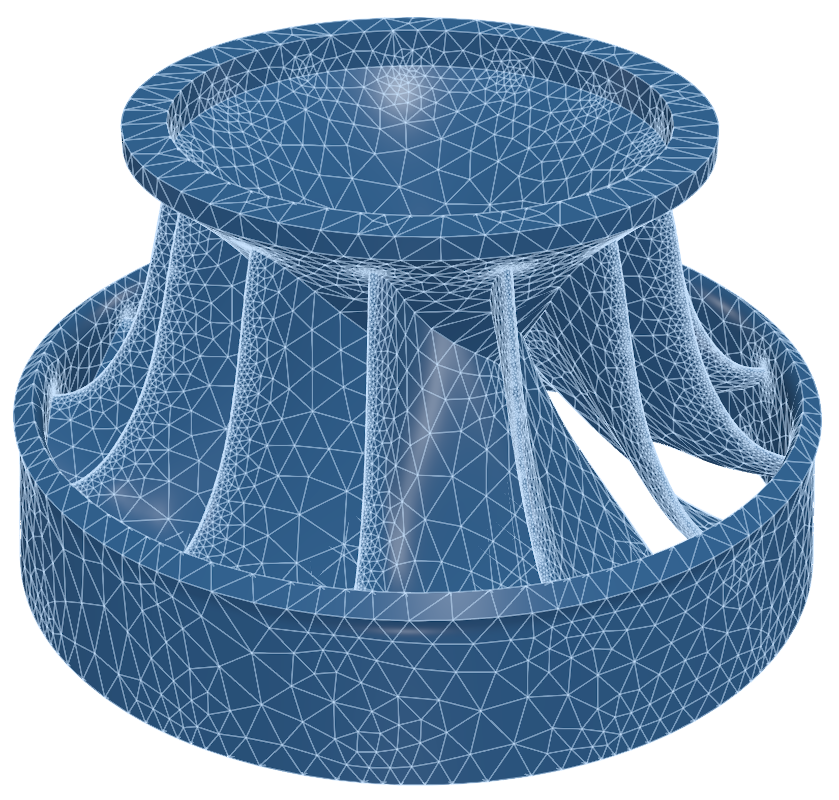
The computational mesh for FEA is created in an automated software module TMESH, using the NetGen open-source application. All the mesh settings can be done in the TCAE GUI.
The closed STL model is meshed with just a little effort because there are just a few parameters to set. The most important parameters for FEA meshing are “h Max” and “h Min” which mean the maximal and minimal mesh edge in meters. The mesh is created with an automated algorithm. For more details, see the TCAE documentation.
Francis Turbine - CFD Simulation Setup
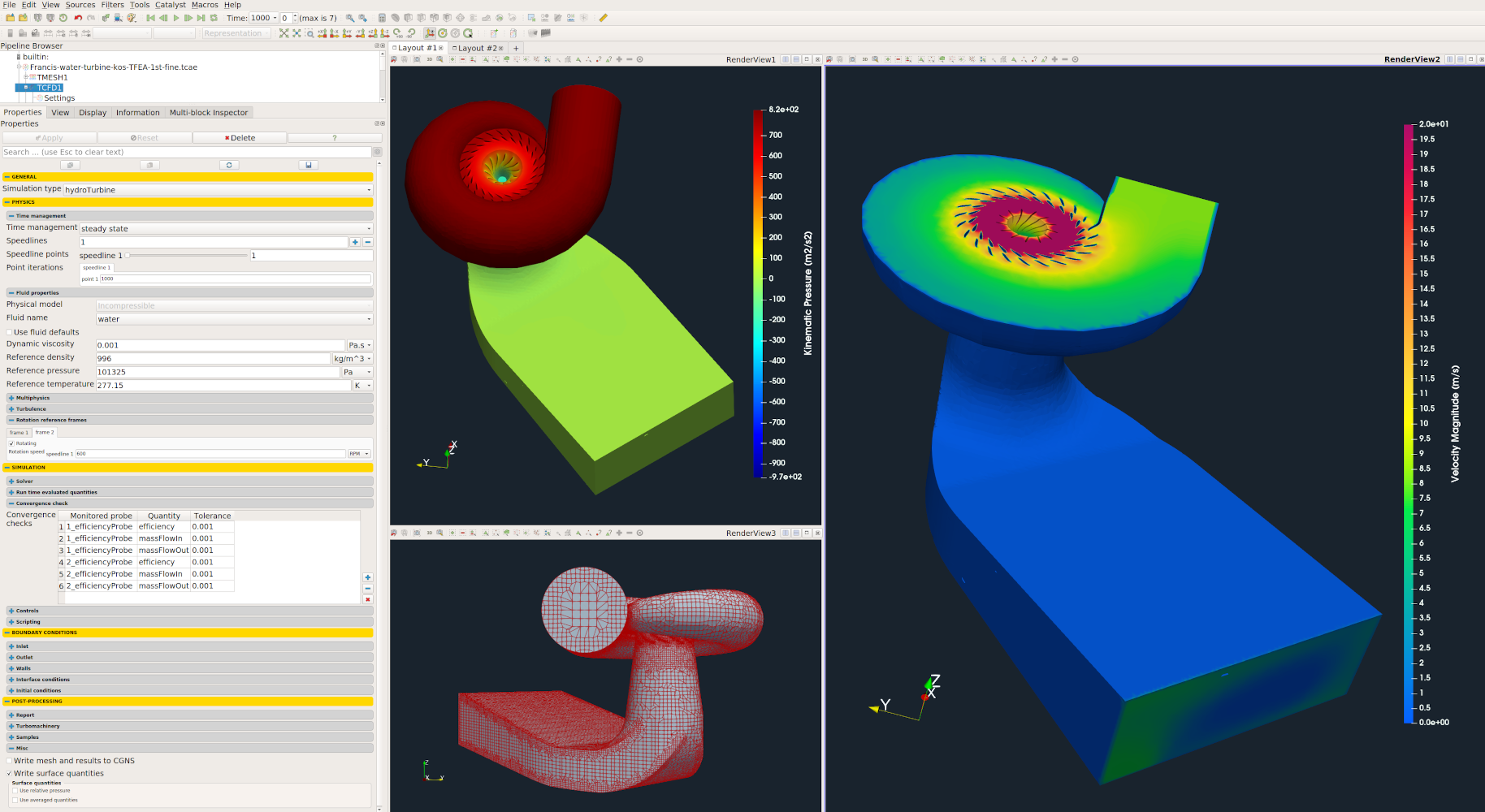
The CFD simulation is managed with TCAE software module TCFD. Complete CFD simulation setup and run is done in the TCFD GUI in ParaView. TCFD uses OpenFOAM open-source application.
Simulation type: Hydro Turbine
Time management: steady-state
Physical model: Incompressible
Number of components: 3 [-]
Wall roughness: none
Physical model: Incompressible
Speed: 600 [RPM]
Outlet: Static pressure 0 [m2/s2]
Turbulence: RANS
Turbulence model: k-omega SST
Wall treatment: Wall functions
Turbulence intensity: 5%
Speedlines: 1 [-]
Simulation points: 10 [-]
Fluid: Water
Reference pressure: 1 [atm]
Dynamic viscosity: 1.0 × 10E-3 [Pa⋅s]
Water density: 996 [kg/m3]
CFD CPU Time: 1.5 core.hours/point
BladeToBlade: on
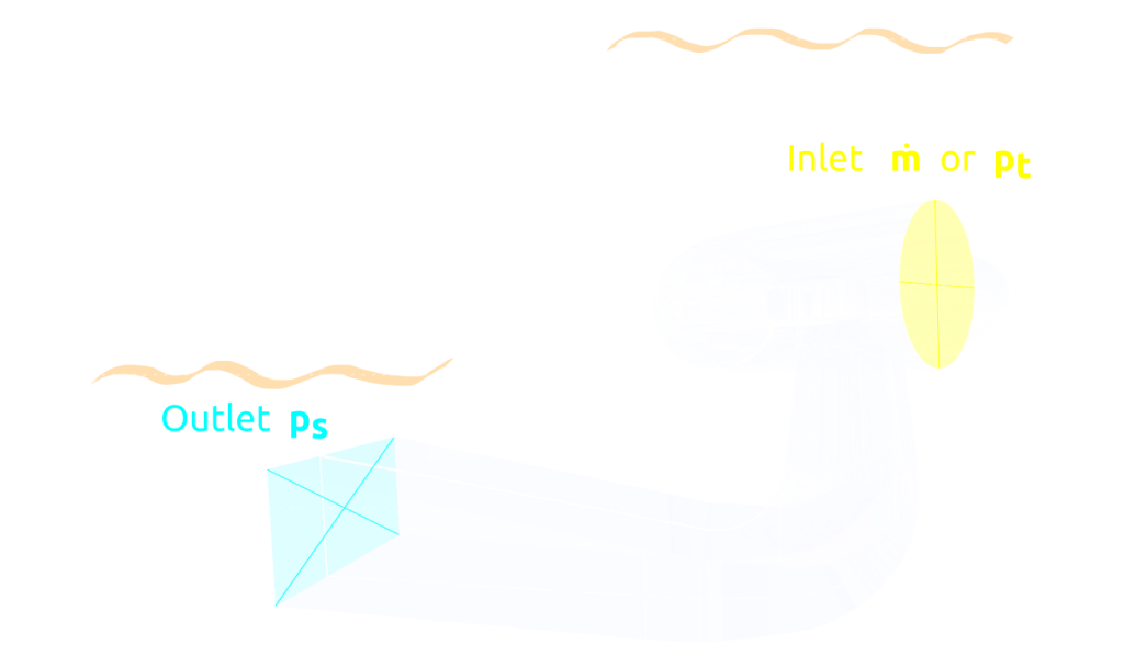
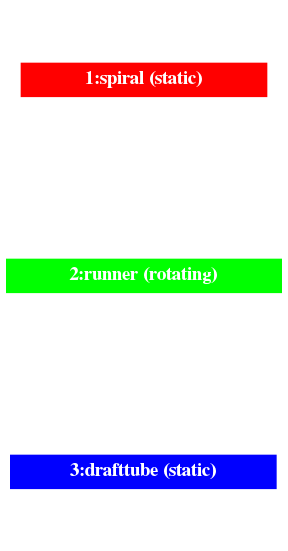
Any project simulated in TCFD has its component graph. The component graph shows the way the components are organized – the model topology. It shows for instance what is the inlet, the outlet and the way the components are connected via interfaces. A simple scheme of the component graph is shown below. The fluid flow enters the facility in the component Spiral via interface spiral_inflow_inlet and leaves the facility from the component drafttube via interface drafttube_outflow_outlet. This is a typical example of a very simple linear order of the flow, through a combination of three components.
Francis Turbine - FEA Simulation Setup
The FEA simulation is managed with TCAE software module TFEA. Complete FEA simulation setup and run are done in the TFEA GUI in ParaView. TFEA uses Calculix open-source application.
Beam material: steel
Material density: 7800 kg/m3
Material structure: isotropic
Young modulus: 2.1E11 Pa
Poisson ratio: 0.3
Fixed radius: 100 [mm]
Finite element order: second
FEA CPU Time: 0.02 core.hours/point
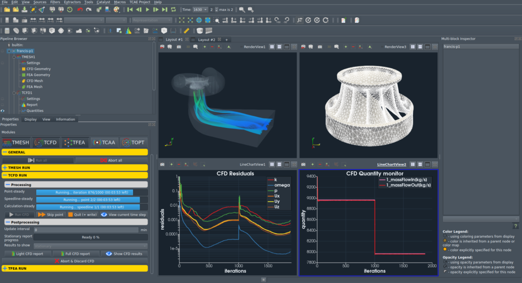
Francis Turbine - TCAE Simulation run
The TCAE simulation run is completely automated. The whole workflow can be run by a single click in the GUI, or the whole process can be run in the batch mode on a background. Modules used are TCAD, TMESH, TCFD, and TFEA. TCFD includes a built-in post-processing module that automatically evaluates all the required quantities, such as efficiency, torque, forces, force coefficients, flow rates, pressure, velocity, and much more. All these quantities are evaluated throughout the simulation run, and all the important data is summarized in an HTML report, which can be updated anytime during the simulation, for every run. All the simulation data are also saved in tabulated .csv files for further evaluation. TCFD is capable of writing the results down at any time during the simulation. The convergence of basic quantities and integral quantities are monitored still during the simulation run. The geometry was created just one-time in the beginning using TCAD in the preprocessing phase. First, the TMESH is executed to create the volume meshes for CFD & FEA. Then the CFD simulation is executed and evaluated. After that, in the FSI step, the pressure field is integrated to create the force field which is prescribed as a load for the FEA simulation. Finally, the FEA simulation is executed and evaluated.
Francis Turbine - Postprocessing - Integral Results
All the integral results (efficiency, torque, head, …) are automatically evaluated and saved in the .CSV files and are available for further postprocessing if needed. The simulation results are evaluated automatically. Every simulation run in TCAE has its own unique simulation report. The integral results both for CFD and FEA are written down in the following HTML or PDF reports:
The simulation reports have countless options and gether togother many useful information and simulation statistics inclufing for example the following plots (and many more):
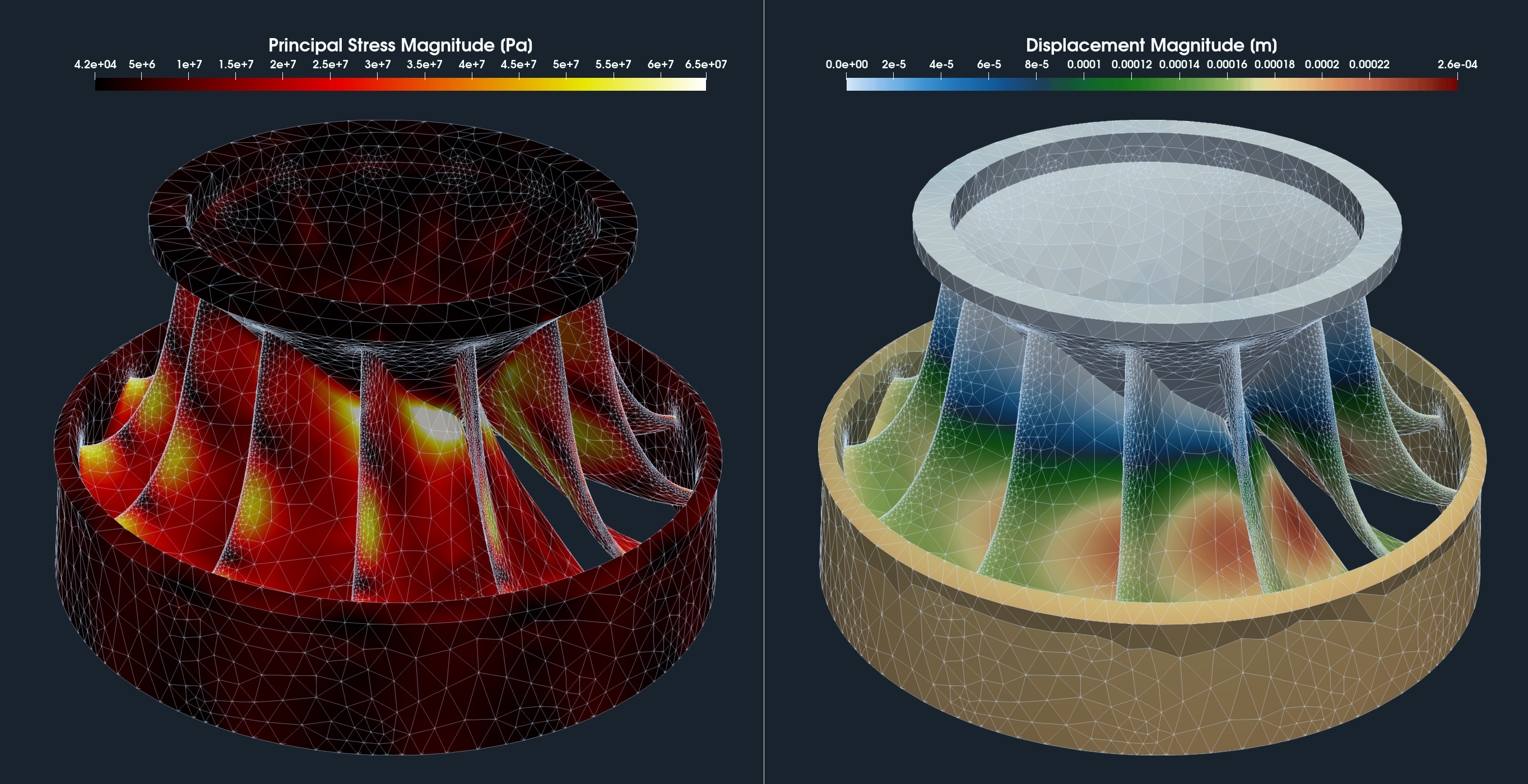
Francis Turbine - Postprocessing - Volume Fields
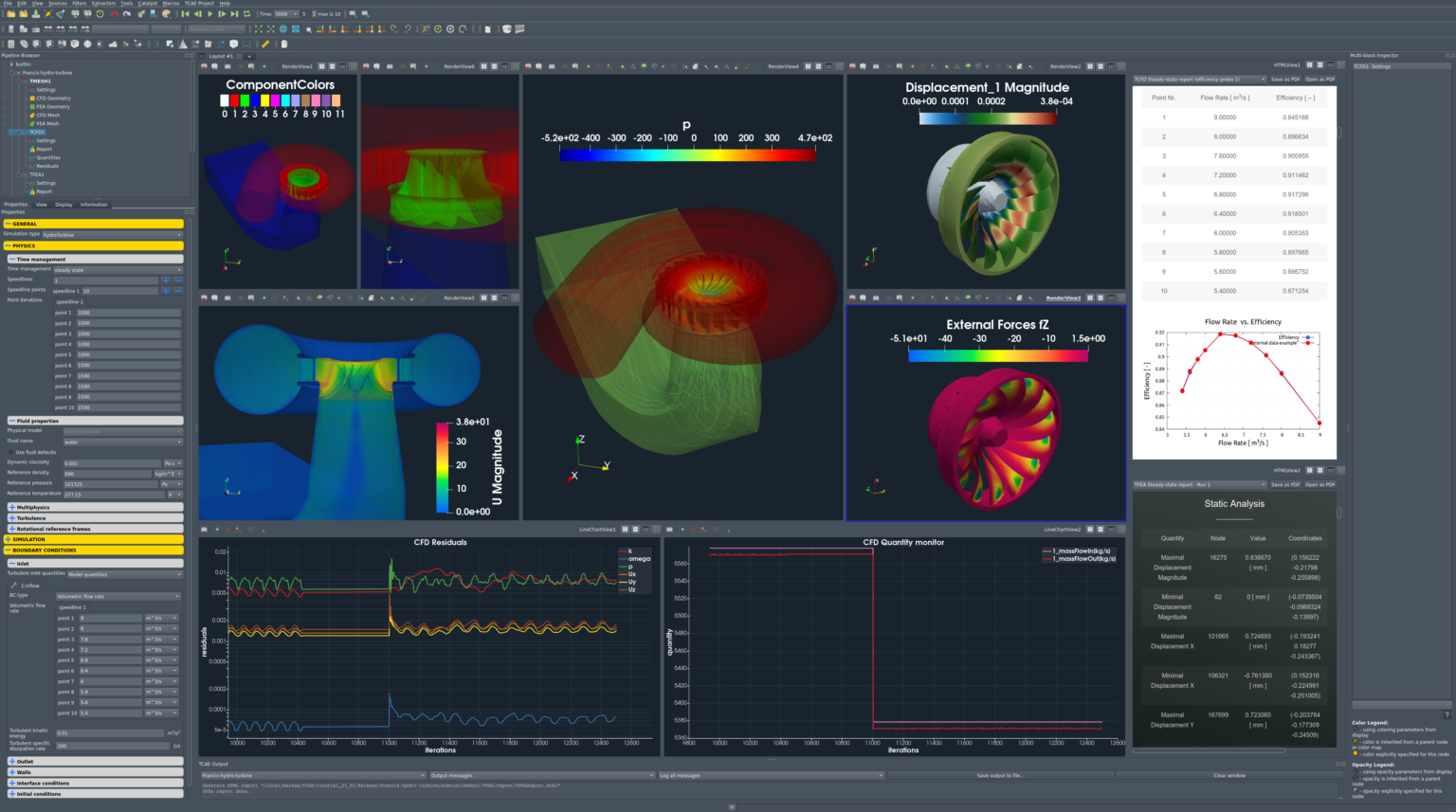
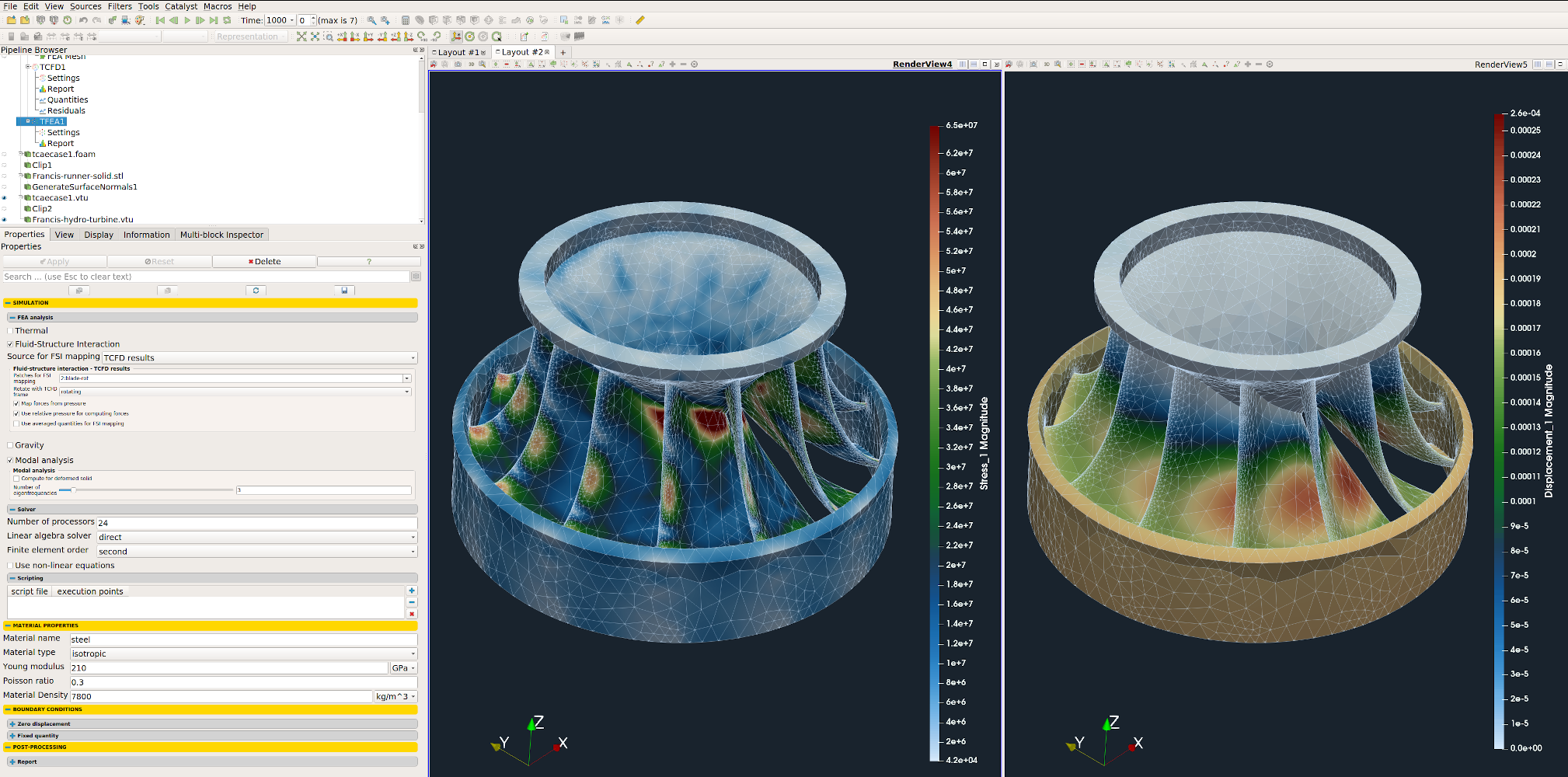
The volume fields are post-processed in the TCAE graphical interface (GUI) which is based on the open-source visualization tool ParaView. ParaView provides a wide range of tools and advanced methods for CFD & FEA postprocessing and results evaluation. There are available countless useful filters and sources, for example: Calculator, Contour, Clip, Slice, Threshold, Glyph (Vectors), Streamtraces (Streamlines), and many others.
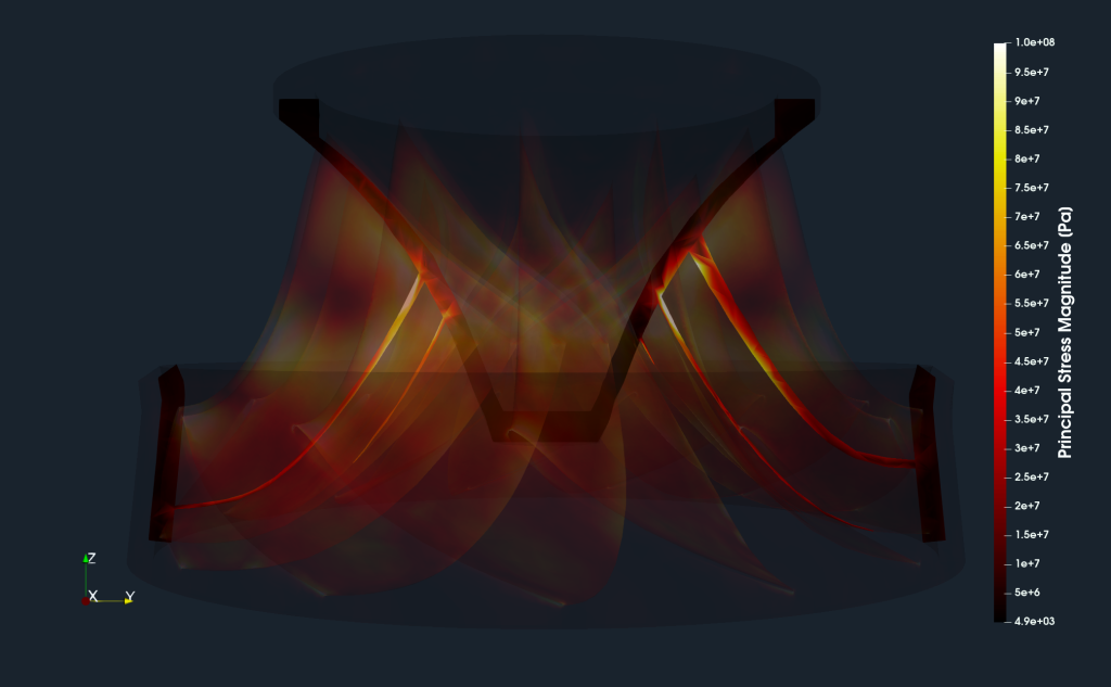
The two following images show a simple surface plot of the Francis turbine runner. The displayed quantities are the principal material stress in Pascals and material deformation (displacement) in meters.
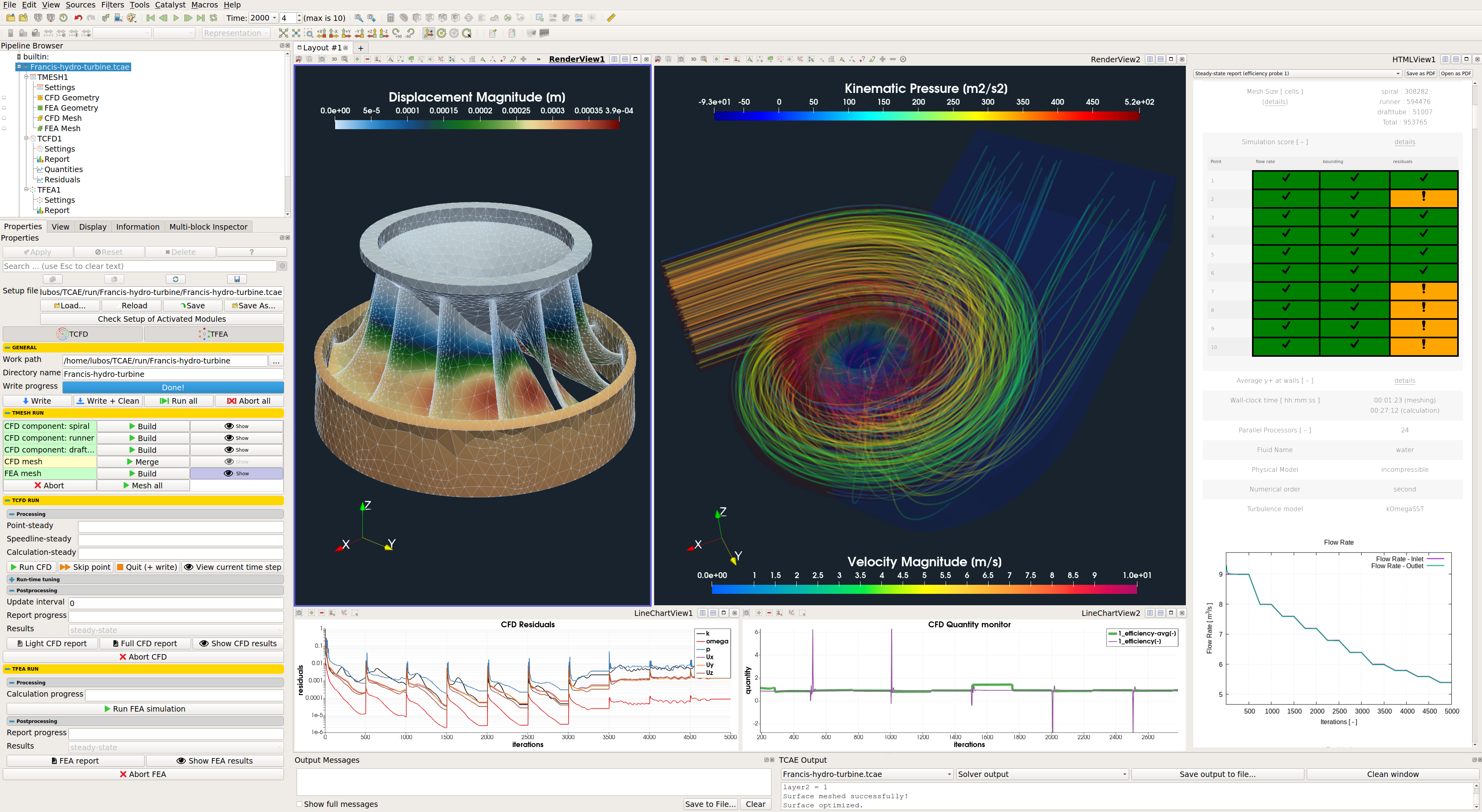
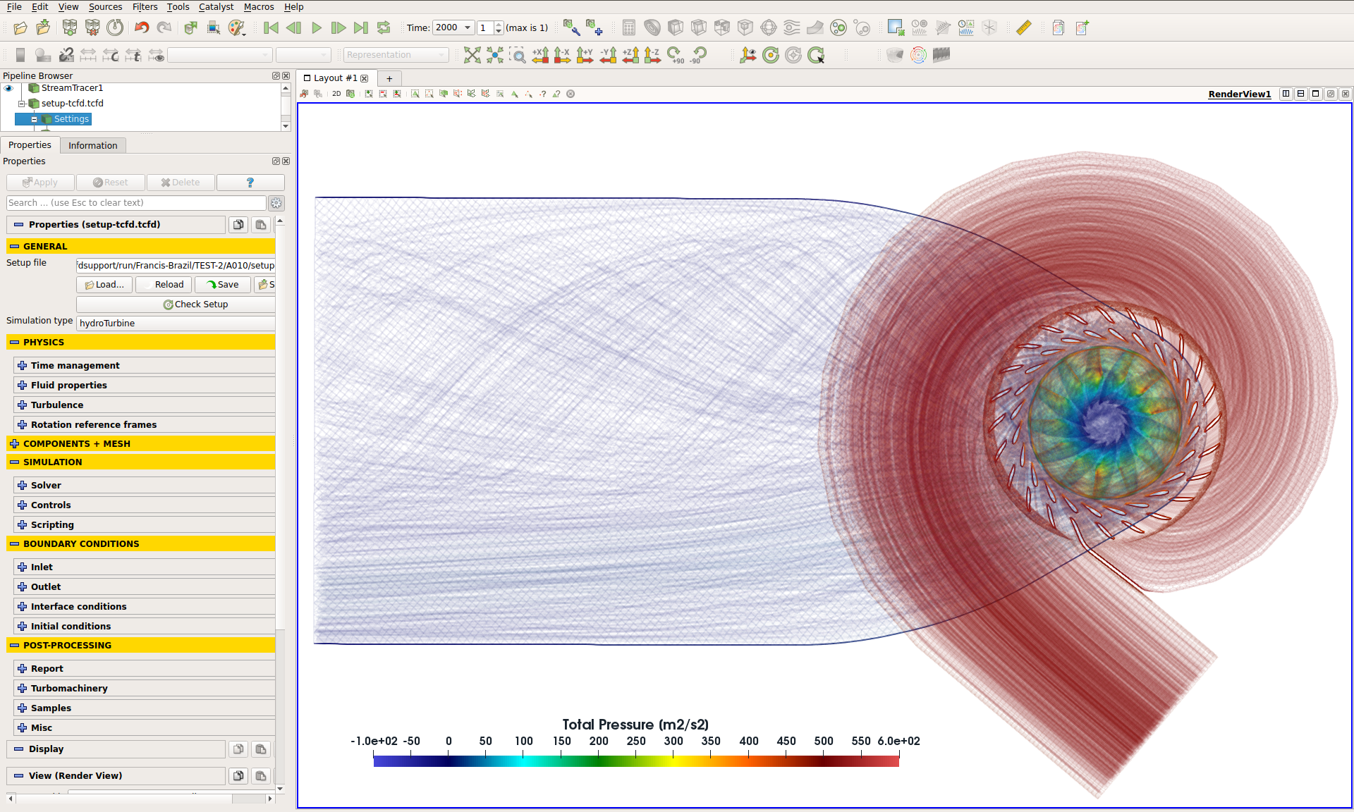
The following image shows an example of the way how the postprocessing graphical interface looks like.
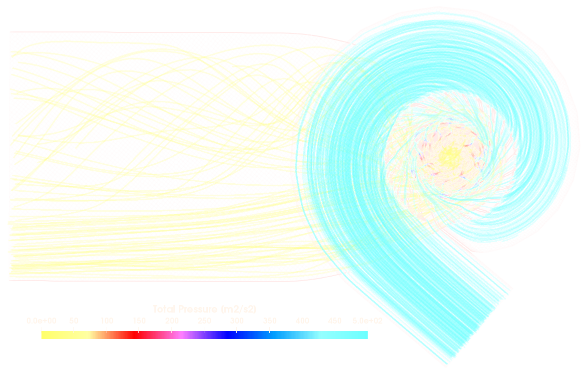
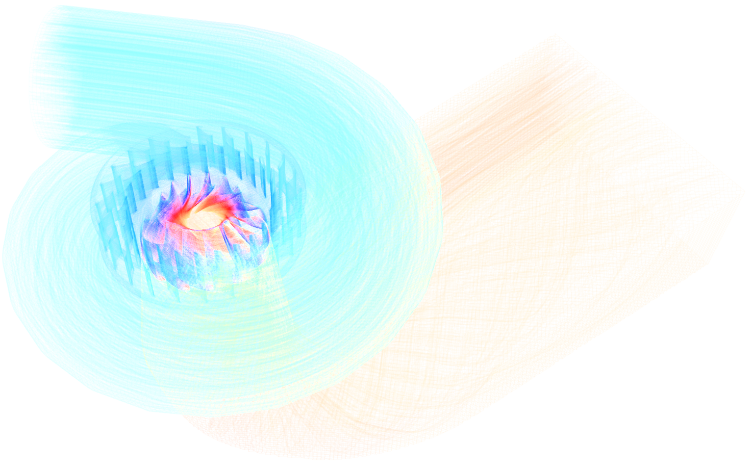
The following image shows an example of the streamtraces colored by the kinematic total pressure in m2/s2.
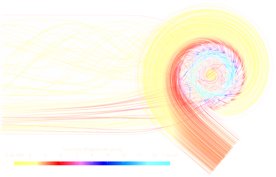
The following image shows an example of the streamtraces colored by the flow velocity in m/s.
The following image shows an example of the streamtraces colored by the kinematic total pressure in m2/s2.
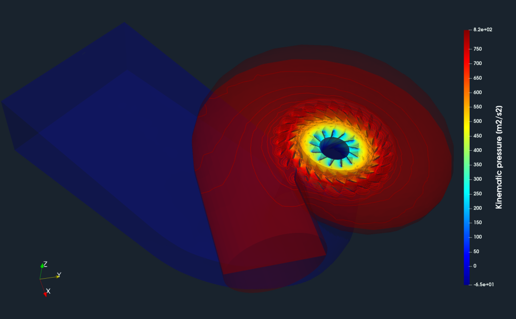
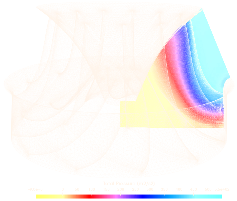
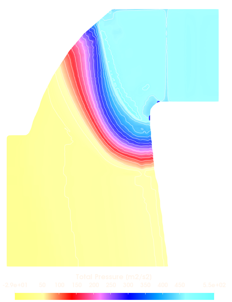
The following image shows an example of the slice colored by the kinematic total pressure in m2/s2 and its pressure contours.
The following image shows an example of the slice colored by the principal stress in Pa.
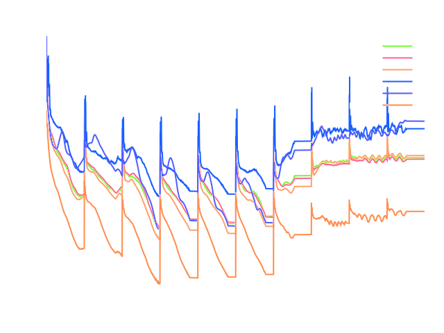
Francis Turbine - Benchmark Results - Power
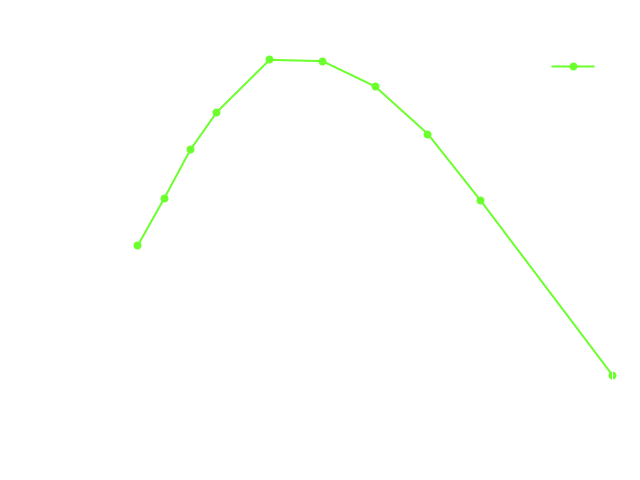
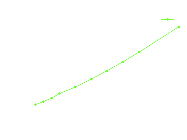
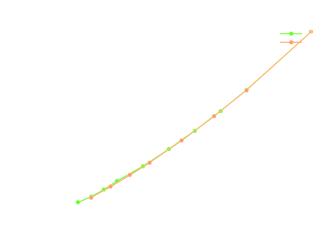
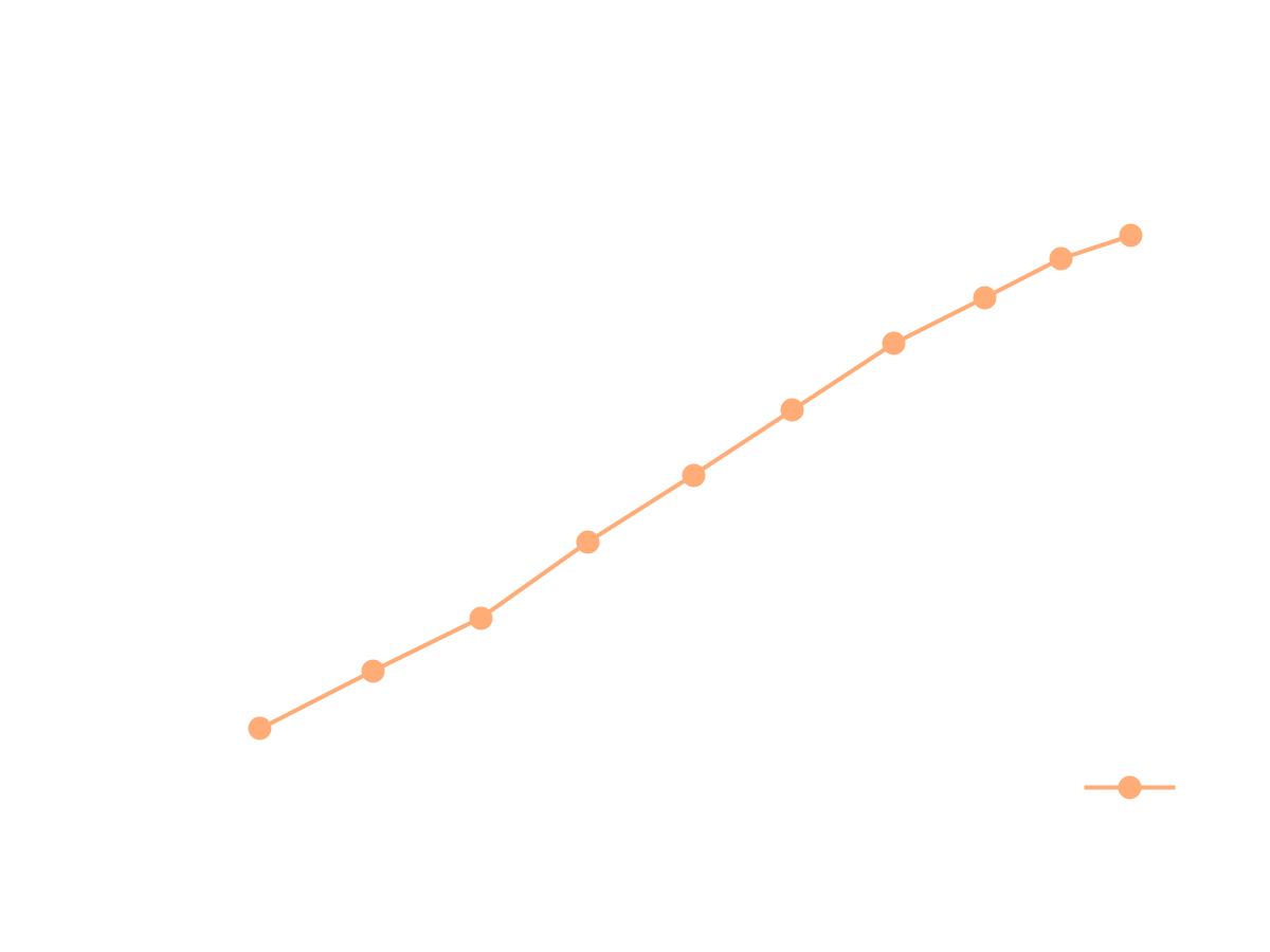
A very important result of hydro turbine simulation is turbine torque, which is a result of fluid flow pressure and viscous forces acting on the impeller surface. The resulting turbine power is calculated from a simple formula P = T · ω Where P is power [W], T is torque [N.m], and ω is angular velocity [rad/s]. The image on the right hand side shows the comparison of turbine power from CFD simulation compared to the turbine power gained from the experimental measurement. There were investigated 10 turbine modes (flow rates), corresponding to the 10 guide vanes openings.
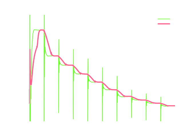
Francis Turbine - Benchmark Results - Efficiency
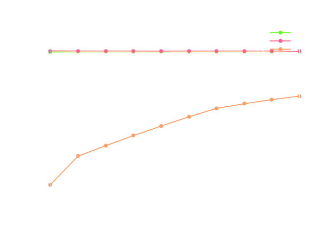
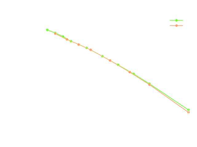
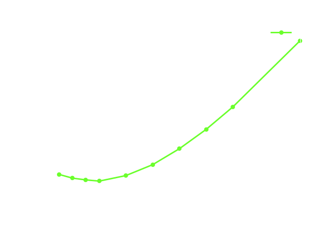
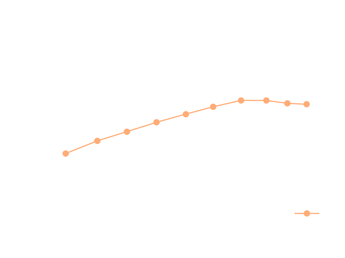
Another very important quantity at hydro turbine is turbine efficiency. Turbine efficiency is a ratio of the gained energy and water column energy potential and can be expressed as: η = P / ( m · g · ϱ · h) Where η is efficiency [-], P is power [W], m is flow rate [m3/s], g is gravitational acceleration [m/s2], ϱ is density [kg/m3], and h is net head, which is the difference between water levels (in the simulation results, the head is obtained from the total pressure difference between the turbine pressure at the inlet and the total pressure at the outlet). Because of the measurement method, the reference head of 47.91 m is considered for all the simulation modes. The image shows the comparison of turbine efficiency from CFD simulation compared to the turbine efficiency gained from the experimental measurement. There were investigated 10 turbine modes (flow rates), corresponding to the 10 guide vanes openings.
Francis Turbine - Meridional Average View
For turbomachinery engineers, it is typically important to see the results, for example, total pressure or velocity, circumferentially averaged and projected on the meridian plane. This method is called the Meridional Average. This meridional average projection avoids the holes (blades) and shows how the total pressure (energy) or velocity are distributed along the meridian (a 2D interpretation of flow through the facility). Another important hydro turbine simulation results evaluation is a visualization of a Meridional Average of simulated quantities. This visualization gives the user valuable information about how, for example, the total pressure is spent in the flow passage of the turbine. A special TCAE filter Meridional Average, created for ParaView, is applied and creates a geometrical slice (a plane), containing the rotation axis and the circumferential averages of all the field data projected onto this slice. The Meridional Average method ignores, for example, blades or other obstacles, and as a result, the resulting averaging plane has a shape of a compact flow passage. The Meridional Average view images are natural part of the automated TCFD report.
Francis Turbine - Blade to Blade View
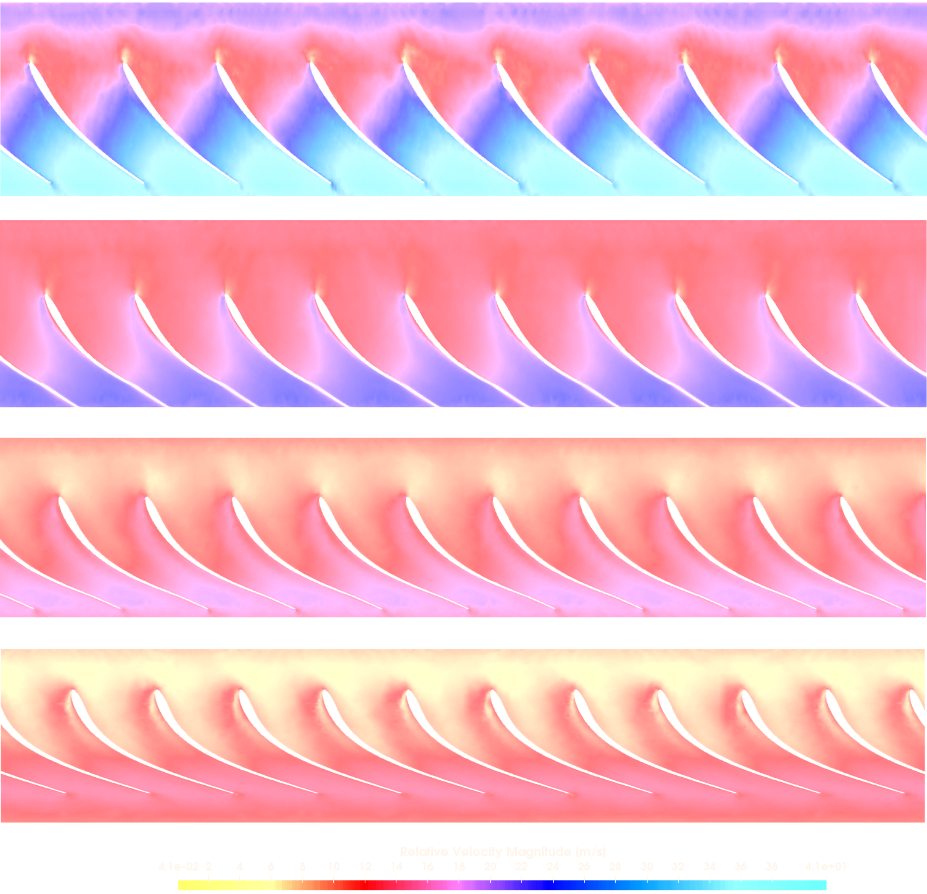
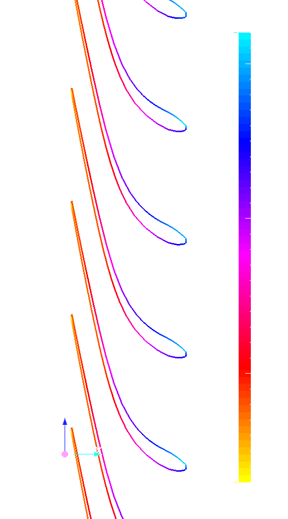
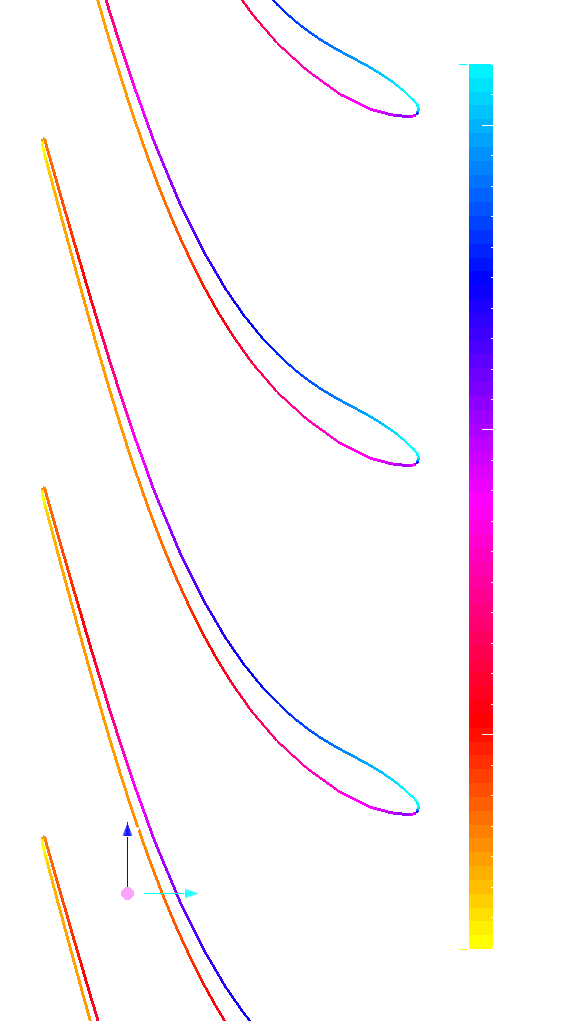
Another important hydro turbine simulation results evaluation is a blade-to-blade view. The blade-to-blade view offers a unique perspective for an inspection of the flow field properties between the blades, at a fixed relative distance between the hub and shroud boundary surfaces (spans). In TCAE, the blade-to-blade view (spans) can be generated in two steps: First, the cylindrical mesh of the rotating zone needs to be transformed (unwrapped) into a normalized rectangular block (1x1x2Pi). Second, the unwrapped block is to be cut at the preferred normal distance (0-1), between hub and shroud. A typically desired field view is, for example, streamtraces of the flow field or relative velocity at the impeller. The user can observe how smoothly the fluid flows and how effectively the fluid attacks the leading edges of the blades. The following images show the streamtraces projected onto blade-to-blade planes in the form of LIC (Line Integral Convolution), colored by the flow field relative velocity.
For the specific opening corresponding to the flow rate of 5.48 m3/s. There are four planes at relative height 0.99, 0.8, 0.6, and 0.4 between hub and shroud. Blade to blade view is a special transformation method that transforms the rotational object (and the CFD results) into the dimensionless hexahedron of the edges of 2phi x 1 x 1. Especially, leading and trailing edges (flow angles) are of the main interest here. The blade-to-blade view images are a natural part of the automated TCFD report.
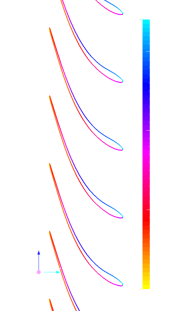
Francis Turbine - Pressure along the Blade
Similar to the blade-to-blade view, in the TCAE GUI, the runner (impeller), a rotationally symmetric object, can be unwrapped (transformed) onto the hexahedron object to be able to slice it to see the computed quantities of the same radial coordinate along the blade. With such an unwrapped model it is also easy to plot the quantities around the blade at any distance between hub and shroud (spans).
Francis Turbine - Particle-like Animation
TCAE offers extensive possibilities for flow visualization. Very typical flow visualization is the visualization of stream traces – the trajectories of the flow. Based on stream traces, it is possible to make a visualization of particle-like flow to enhance the flow details. See the following animation. Imaginary particles enter the Francis turbine spiral approximately at the same time in two emissions. There are several effects to observe. It is interesting to see the way the runner swallows the particles, gradually along the spiral. The flow slows down in the spiral first to accelerate at the guide passage. Some particles stay in the turbine 5-10 times longer than the fastest ones.
Francis Turbine - Model Animation in Blender
Based on the TCAE simulation, it is possible to follow the flow trajectories to view the simulation model from the inside. The following animation shows the Francis turbine model from the inside.
Conclusion
• It has been shown how to make a comprehensive CFD & FEA analysis including FSI and modal analysis of the Francis turbine in a smooth and automated workflow.
• TCAE showed to be a very well suited tool for CFD, FEA, and FSI engineering simulations.

Hi, how are you?