
Centrifugal Pump Optimization
A complete simulation-driven optimization workflow combining fully parametric geometry generation, automated meshing, CFD simulation, design exploration, and optimization.
Improving the hydraulic performance of a centrifugal pump is rarely a matter of changing a single dimension. Blade angles, blade count, impeller width, and volute geometry interact, creating a multidimensional design space that cannot be reliably understood from a few manually selected variants.
7
Design Variables
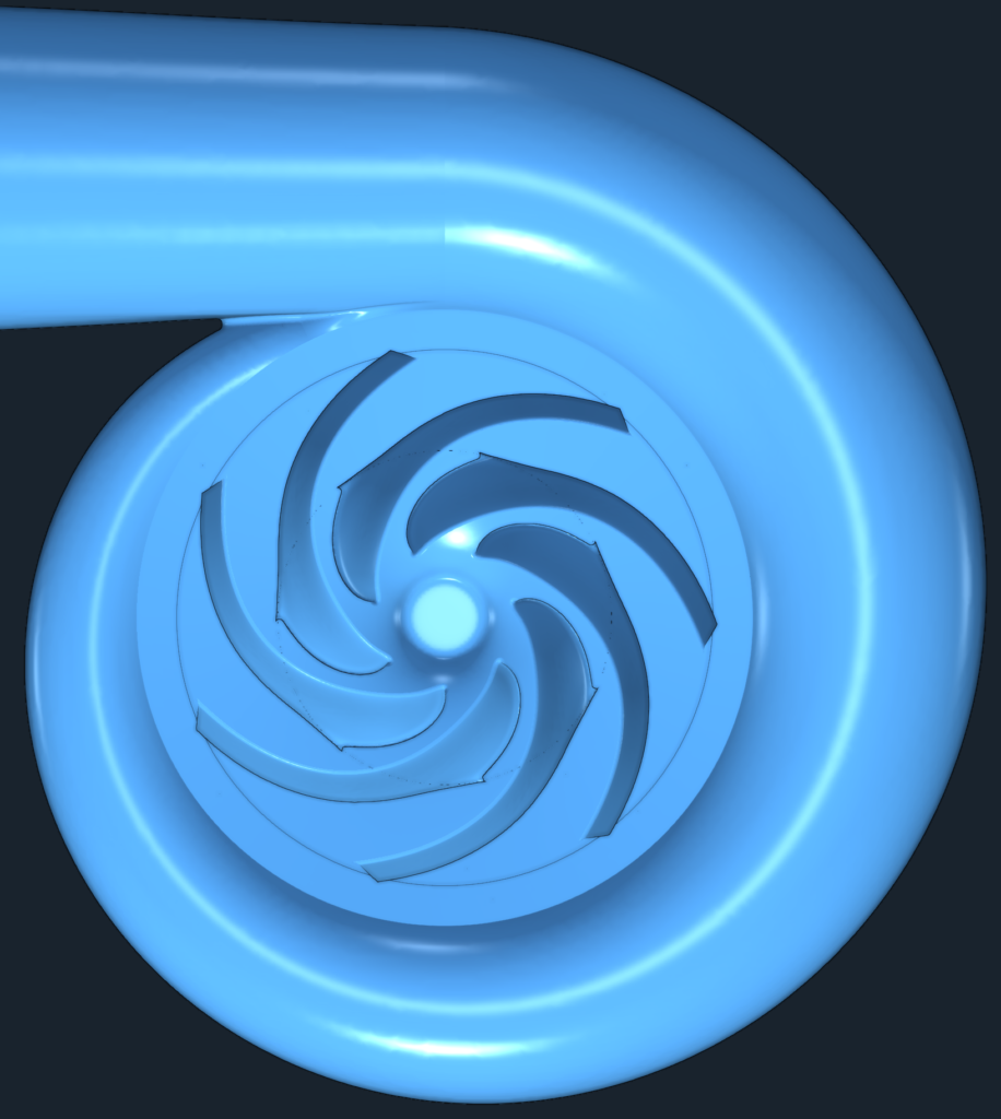
Centrifugal Pump
Real-world geometry
DOE + Optimization
Single Workflow
Maximize
Hydraulic Efficiency
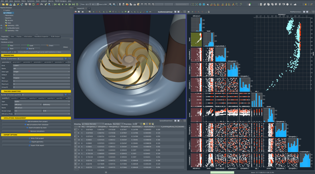
The study explores how pump performance varies across a broad range of feasible geometries. The first 250 designs are generated using Latin Hypercube Sampling to map the design space, followed by 250 Efficient Global Optimization evaluations focused increasingly on promising regions.
The objective is therefore not only to identify a high-efficiency design. Every geometry, parameter set, and CFD result contributes to a reusable dataset that can be stored in TBASE and used for surrogate modelling, sensitivity analysis, future optimization, and engineering decision support.
The optimized pump is one result. The explored design space is the lasting engineering asset.
Why This Study Matters
This study demonstrates a complete simulation-driven optimization methodology for centrifugal pump design. TCAE connects parametric geometry generation, automated meshing, CFD evaluation, design-of-experiments, and surrogate-based optimization within a single repeatable workflow.
The key capability is not a particular optimized geometry, but the ability to systematically explore a multidimensional design space with minimal manual intervention. The same workflow can be reused with different design parameters, operating conditions, objectives, and constraints.
All evaluated designs and simulation results can subsequently be stored in TBASE, transforming individual optimization projects into a growing engineering knowledge base for future design exploration, surrogate modelling, and decision support.
Study Overview
A simple geometry. A complete optimization workflow.
Question
How can the hydraulic efficiency of a centrifugal pump be improved?
The study investigates the influence of key impeller and volute design parameters on pump performance. The objective is to maximize hydraulic efficiency using an automated simulation-driven optimization workflow while maintaining a fully parametric and manufacturable pump geometry.
Approach
Fully automated parametric optimization using CFD
Pump geometry is generated parametrically and evaluated automatically within the TCAE. Each candidate design undergoes geometry generation, meshing, CFD simulation and post-processing without manual intervention.
The optimization combines 250 Latin Hypercube Sampling (LHS) simulations for an initial exploration of the design space with 250 Efficient Global Optimization (EGO) simulations that iteratively identify the most promising design candidates.
Finding
Optimization reveals the structure of the design space, not only its optimum.
The study demonstrates how pump performance varies across hundreds of feasible designs rather than focusing on a single optimized geometry. By systematically exploring combinations of blade angles, blade count, impeller width and volute height, the optimization quantifies the sensitivity of each parameter and identifies robust regions of high hydraulic performance.
This transforms optimization from a search for one solution into a systematic investigation of the underlying engineering behaviour.
Outcome
A reusable optimization workflow and a permanent engineering knowledge base.
The workflow produces far more than a single optimized impeller. Each of the 500 CFD simulations represents a validated engineering experiment describing how geometric modifications influence hydraulic performance.
The complete optimization history—including geometry parameters, CFD results and objective values—can be stored in TBASE, where it becomes part of the company's engineering knowledge base. Future projects can reuse this information to guide new designs, train surrogate models, perform sensitivity analyses or support AI-assisted engineering decisions without repeating previous work.
Rather than ending with a single optimum, the project continuously increases the value of the company's engineering know-how.
Engineering Challenge
How can a complex pump design space be explored systematically?
Improving centrifugal pump performance involves several strongly interacting geometric parameters. Blade angles, blade count, impeller width, and volute geometry cannot be assessed independently, while evaluating all possible combinations directly with CFD is computationally impractical.
The challenge is therefore not only to find a better design, but to establish a fully automated and repeatable methodology for exploring the design space. Each candidate geometry must be generated, meshed, simulated, and evaluated consistently, allowing optimization algorithms to guide the search while minimizing manual intervention.
This is scientifically stronger because it establishes three things immediately:
multidimensionality → computational cost → automation as the solution.
And it prepares the reader naturally for the next section: Design Variables / Parametric Geometry.
Simulation Workflow
From design variables to engineering knowledge.
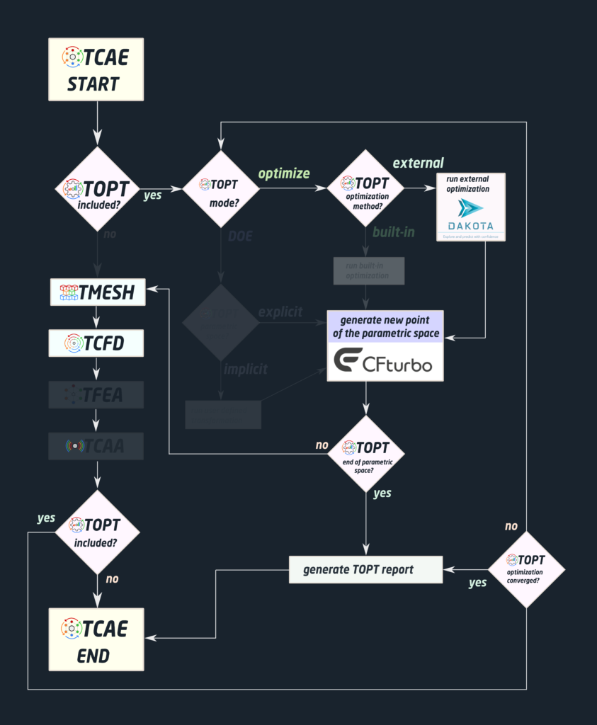
The optimization process is structured as an automated loop that connects geometry generation, meshing, CFD simulation, and design optimization.
The loop starts with a set of design variables; a new geometry is automatically created and passed to the meshing stage. The generated mesh is then evaluated using CFD simulations, where hydraulic performance is assessed based on the pump efficiency.
The optimization algorithm analyzes the results, identifies promising design candidates, and proposes new parameter combinations for evaluation. This process continues until the specified stopping criteria are reached.
Because every step is automated, hundreds of design variants can be evaluated without manual intervention. At the same time, all simulation parameters, performance metrics, and results are systematically stored, creating a reusable foundation for future design exploration, surrogate modeling, and engineering knowledge extraction.
Automation replaces repetitive work, allowing engineers to focus on design decisions rather than simulation execution.
CFD Simulation Setup
Geometry Builder
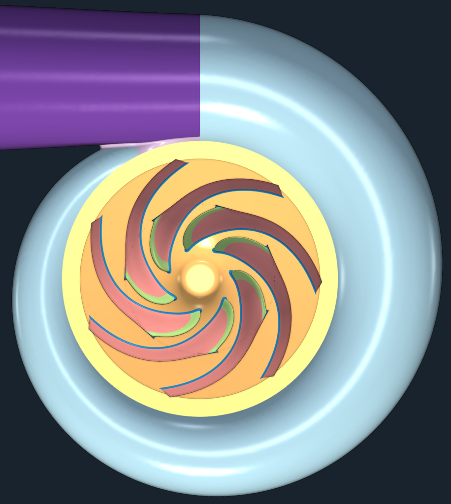
The workflow uses the turbomachinery design software CFturbo to create the pump geometry. The entire execution loop is defined in the TOPT script, which runs the CFturbo geometry generation on a local Windows computer, while the CFD simulation runs on Linux infrastructure, typically a Linux cluster.
Mesh
Automated Mesh Generation
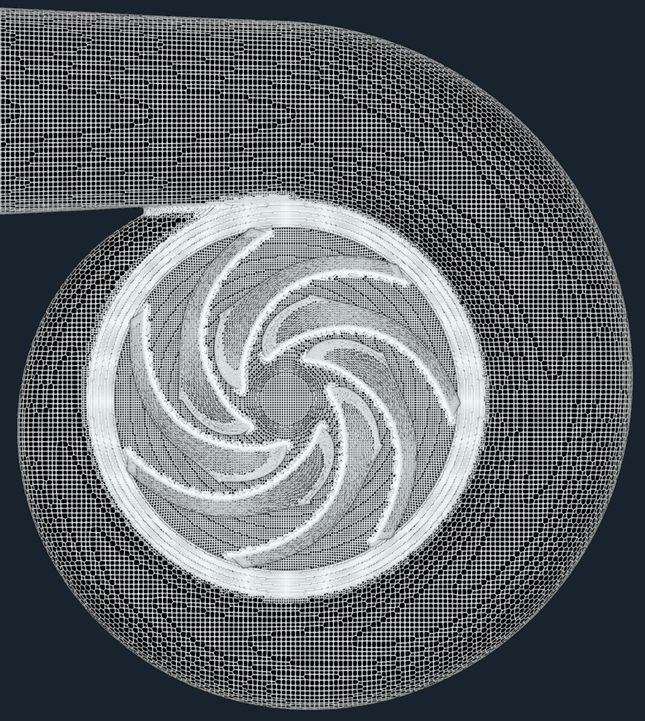
Each candidate geometry is meshed automatically using snappyHexMesh within TCAE. A hex-dominant mesh is generated with local refinement around the impeller blades, volute walls, and other regions with strong geometric curvature and expected flow gradients. Three boundary-layer cell layers are applied at solid walls to improve near-wall resolution.
The same meshing strategy is used for every design candidate, providing a consistent and repeatable CFD discretization throughout the optimization process, despite changes in blade angles, blade count, impeller width, and volute geometry.
Physics
Steady-state Turbulent Flow
The simulation considers steady, incompressible turbulent flow through the centrifugal pump. The primary objective is to evaluate the pump hydraulic performance and determine the resulting hydraulic efficiency.
The working fluid is water, treated as an incompressible Newtonian fluid with constant density and dynamic viscosity corresponding to 20 °C. The operating conditions correspond to fully turbulent internal flow.
Turbulence is represented using the k-ω SST model, which combines the near-wall behavior of the k-ω formulation with the free-stream characteristics of the k-ε model. The model is well suited to turbomachinery applications involving adverse pressure gradients, boundary-layer separation, and strong streamline curvature.
Impeller rotation is modeled using the Multiple Reference Frame (MRF) approach, providing a steady-state representation of the interaction between the rotating impeller and the stationary pump domain.
The governing equations are solved using a finite-volume steady-state incompressible RANS solver. Pressure and velocity are coupled iteratively until the numerical residuals reach the prescribed convergence criteria and the monitored hydraulic performance quantities become stable.
- Simulation type: Pump
- Time management: steady-state
- Physical model: Incompressible
- Number of components: 4 [-]
- Wall roughness: none
- Physical model: Incompressible
- Outlet: Static pressure 0 [m2/s2]
- Turbulence: RANS
- Turbulence model: k-omega SST
- Wall treatment: Wall functions
- Turbulence intensity: 5%
- Speedlines: 1 [-]
- Simulation points: 1 [-]
- Fluid: Water
- Reference pressure: 1 [atm]
- Dynamic viscosity: 1.0 × 10E-6 [Pa⋅s]
- Ref density: 996 [kg/m3]
- CFD CPU Time: 0.1 core.hours/point
- FLow rate: 0.15 [m3/s]
- FLow rate: fixed at the outlet
Boundary Conditions
Fixed Flow Rate
The pump operates at a prescribed flow rate of 150 l/s at the outlet and zero static pressure at the inlet, with standard BCs for all other quantities. The efficiency probes are located at the inlet and at the outlet of the whole computational domain. All the quantities, when averaged, are weighted by the flow rate.
- Inlet: Static pressure 0 [m2/s2]
- Outlet: Volumetric flow rate 150 [l/s]
- Mesh motion: Static, MRF
- Rotation speed: 1770 [RPM]
Optimization Setup
Selected Design Parameters
This particular case study uses 7 variable parameters, but this is completely optional. The user can choose any number of parameters.
Seven design variables were selected:
- Leading Edge Angle Shroud [rad]
- Leading Edge Angle Hub [rad]
- Trailing Edge Angle Shroud [rad]
- Trailing Edge Angle Hub [rad]
- Number of Blades [-]
- Impeller Width [m]
- Volute Height [m]
Together, these parameters define both the impeller and volute geometry while preserving a realistic and manufacturable pump design throughout the optimization process.
Parametric Space
| Parameter | Minimum | Baseline | Maximum |
|---|---|---|---|
| Leading Edge Angle Shroud | 0.22 | 0.325 | 0.42 |
| Leading Edge Angle hub | 0.6 | 0.701 | 0.8 |
| Trailing Edge Angle Shroud | 0.27 | 0.376 | 0.47 |
| Trailing Edge Angle Hub | 0.35 | 0.456 | 0.55 |
| Number of Blades | 4 | 7 | 11 |
| Impeller Width | 0.032 | 0.037 | 0.042 |
| Volute Height | 0.1 | 0.15 | 0.2 |
DOE + Optimization
The optimization strategy combines an initial Design of Experiments (DOE) phase with a subsequent surrogate-based global optimization phase. The purpose is to first obtain a representative description of the multidimensional design space and then use the accumulated information to select increasingly valuable CFD evaluations.
Latin Hypercube Sampling = Design Space Exploration
The first 250 design candidates are generated using Latin Hypercube Sampling (LHS) in Dakota. LHS is a stratified sampling method in which the admissible range of each design variable is systematically sampled, providing broad coverage of the seven-dimensional parameter space without requiring an exhaustive combination of all parameter values.
At this stage, the objective is exploration rather than optimization. Designs with both low and high hydraulic efficiency are valuable because they establish the initial relationship between geometry parameters and pump performance. This dataset provides the training information required for the subsequent surrogate-based optimization.
Efficient Global Optimization = Adaptive Search
The second 250 evaluations use Efficient Global Optimization (EGO) in Dakota. EGO constructs a Gaussian-process (Kriging) surrogate model of the objective function from the simulations already available. Unlike a conventional optimization method that evaluates candidate points directly with CFD, the surrogate provides both a predicted objective value and an estimate of prediction uncertainty across unsampled regions of the design space.
New CFD evaluations are selected using the Expected Improvement acquisition function. This criterion balances two competing objectives: exploitation, where the surrogate predicts designs that may improve the best-known hydraulic efficiency, and exploration, where prediction uncertainty remains high because insufficient data are available. After each new CFD evaluation, the result is added to the dataset and the surrogate model is updated before selecting the next candidate.
The resulting workflow therefore evolves from broad, space-filling exploration toward an increasingly informed search of promising regions—while continuing to collect information about parts of the design space where the model remains uncertain.
Results
500 simulations
Objective Function Evolution
Efficiency Improvement
The baseline design achieves a hydraulic efficiency of 91.08%, while the best evaluated design reaches 94.02%. This corresponds to an improvement of 2.94 percentage points, or approximately 3.2% relative to the baseline.
Although the resulting geometric changes are relatively modest, their combined effect produces a measurable improvement in hydraulic performance. The study demonstrates how systematic exploration of several interacting design variables can identify advantageous parameter combinations that would be difficult to discover through manual trial-and-error modifications.
More importantly, the result validates the complete simulation-driven optimization workflow: from parametric geometry generation and automated CFD evaluation to DOE, surrogate-based optimization, and systematic capture of the resulting engineering knowledge. The optimized geometry is one outcome; the explored design space and the accumulated simulation data provide reusable information for future design decisions.
The optimized geometry is one outcome; the explored design space is the reusable asset. It fits the purpose of this case study much better than simply celebrating a 3% improvement.
Engineering Ensights
Optimization produces designs. Simulations produce results. Knowledge produces better decisions.
Insight 1: Parameterization Defines What the Optimization Can Discover
A good optimization starts with a meaningful design space.
Seven geometric parameters were selected to describe modifications of both the impeller and volute: leading- and trailing-edge blade angles at the hub and shroud, blade count, impeller width, and volute height.
The parameterization provides sufficient freedom to generate substantially different pump designs while preserving geometries that remain suitable for automated generation, meshing, and CFD evaluation. The optimization can only discover solutions that are represented within this predefined design space.
Insight 2: Pump Parameters Cannot Be Considered Independently
Hydraulic performance results from interactions between several geometric features.
Impeller blade angles, blade count, impeller width, and volute geometry influence the flow field simultaneously. A modification that is beneficial for one configuration may have a different effect when combined with changes to other parameters.
The optimization therefore searches combinations of design variables rather than optimizing individual dimensions independently. This is particularly important in turbomachinery, where impeller and volute performance are strongly coupled.
Insight 3: Exploration and Optimization Serve Different Purposes
Understanding the design space comes before exploiting it.
The initial Latin Hypercube Sampling stage deliberately evaluates designs distributed across the admissible parameter space. Both poor and high-performing configurations are useful because they provide information about the relationship between geometry and hydraulic performance.
The subsequent EGO stage uses the accumulated simulation data to guide new evaluations toward designs that are either promising or informative. The two stages therefore complement each other: DOE builds knowledge of the design space; optimization uses that knowledge to search more efficiently.
Insight 4: Moderate Geometric Changes Can Produce Measurable Performance Gains
Improvement does not necessarily require a radical redesign.
The baseline pump achieves a hydraulic efficiency of 91.08%, while the best evaluated design reaches 94.02%. This represents an increase of 2.94 percentage points, corresponding to approximately 3.2% relative improvement.
The result demonstrates the value of systematically exploring combinations of geometric parameters that would be difficult to identify through manual trial-and-error design modifications.
Insight 5: Automation Makes Large Design Studies Repeatable
Engineers should define the problem and interpret the results—not manually execute hundreds of simulations.
Geometry generation, meshing, CFD solution, post-processing, and objective-function evaluation are performed automatically for every candidate design. The same numerical methodology is applied throughout the study, providing consistency across a large number of geometrically different configurations.
Once established, the workflow can be reused with different parameter ranges, operating conditions, objectives, constraints, or even different pump geometries.
Final Insight: The Optimum Is Only One Result
The explored design space is the lasting engineering asset.
The 500 simulations create a structured dataset linking geometric parameters to hydraulic performance. Instead of discarding this information once the best design has been identified, the complete optimization history can be stored in TBASE and reused for surrogate modelling, sensitivity analysis, design-space exploration, and future engineering decisions.
A new optimization project therefore does more than improve today’s pump. It adds new information to a growing engineering knowledge base that can support the next design problem.
Knowledge Extraction
Beyond the Best Design
The optimized geometry is only one outcome of the study. The optimization process generated a complete dataset containing design variables, CFD results, and performance metrics for every evaluated design.
Design Space Exploration
The generated dataset can be used to identify parameter sensitivities, design trends, and performance correlations that would be difficult to discover from individual simulations.
Foundation for Surrogate Models
Once sufficient simulation data is available, surrogate models can be trained to predict performance almost instantly, enabling rapid design exploration and decision support.
Building Engineering Knowledge
By systematically capturing simulation inputs and outputs, optimization studies evolve from isolated projects into reusable engineering knowledge assets. TBASE can save results from multiple studies and create surrogate models without requiring expensive simulations.
Downloads & Resources
centrifugal-pump-optimization-TCAE-Tutorial.zip
File size: 8.5 MB
Tutorial Features: PUMP, OPTIMIZATION, CFD, TCAE, TMESH, TCFD, SIMULATION, INCOMPRESSIBLE FLOW, STEADY-STATE, AUTOMATION, WORKFLOW, SNAPPYHEXMESH, 4 COMPONENTS, 3D, Finite Volume, CFD, OpenFOAM, k-ω-SST