CFD SUPPORT introduces the new generation of CFD simulations. TCFD brings an extreme increase of productivity to CFD simulations. TCFD is extremely popular project, because it successfully merged benefits of an open-source (perpetual, unlimited users, jobs, and cores, customizable, …) with benefits of commercial codes (professional support, well tested, ready for the industry, robust, accurate, automated, GUI, …).
The input data
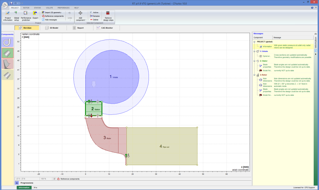
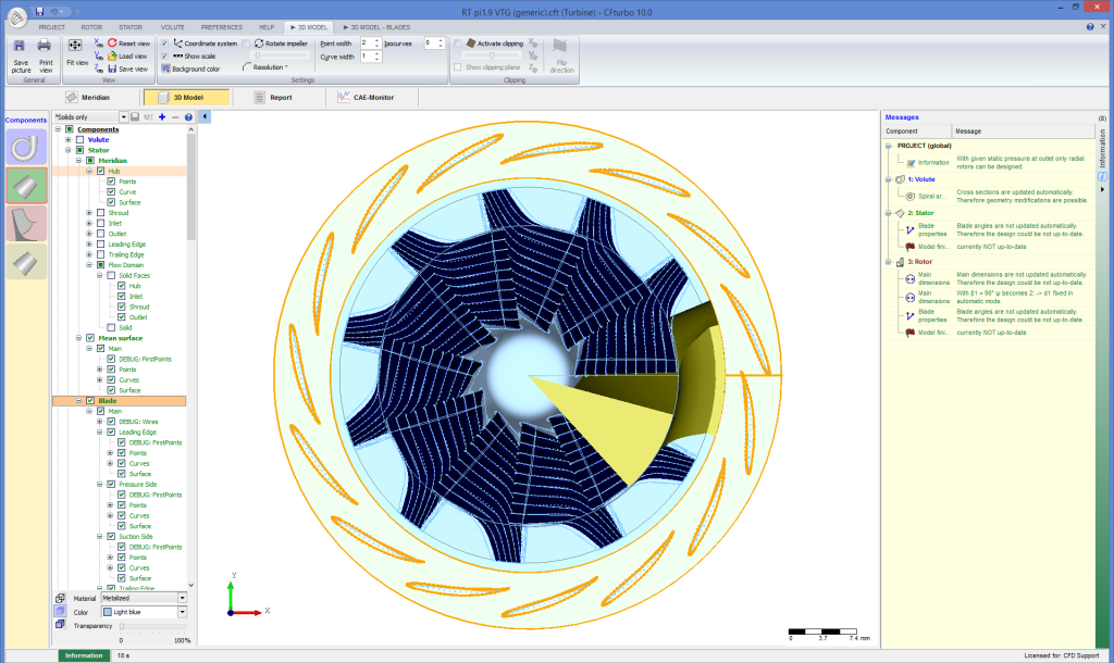
The turbine model is designed in CFturbo®. CFturbo® is a modern, powerful software for interactive design of turbomachinery. It’s easy to use and enables the designer to either start from scratch or redesign existing geometries.
The designed model data are exported from CFturbo®. The surface model data in .stl file format together with physical inputs are loaded in TCFD. Other option would be loading an external mesh in OpenFOAM® mesh format, or loading an MSH mesh format (Fluent mesh format). This CFD methodology employs a multi component approach, which means the model is split into a certain number of regions. In TCFD each region can have its own mesh and individual meshes comunicate via interfaces.
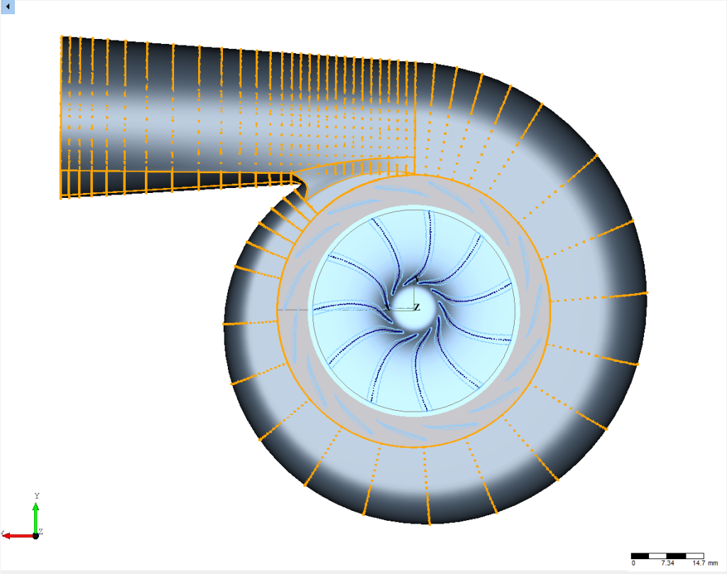
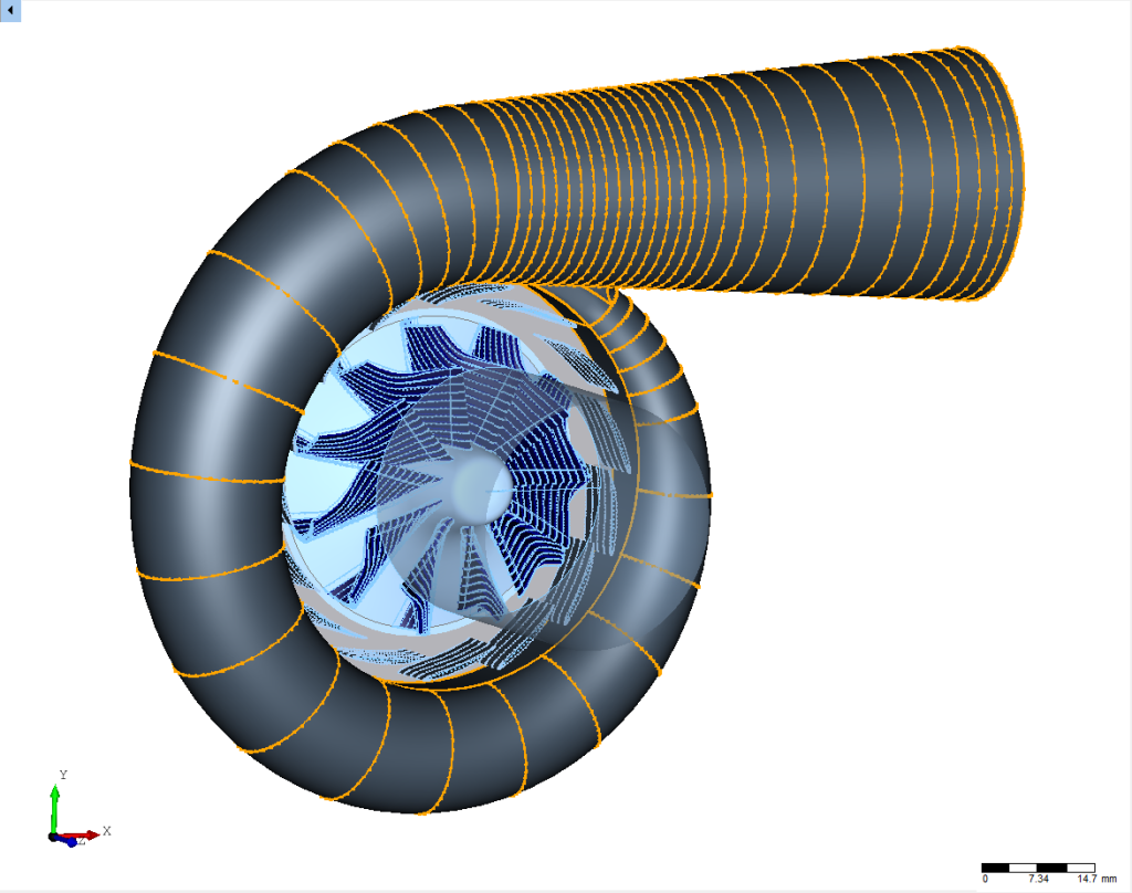
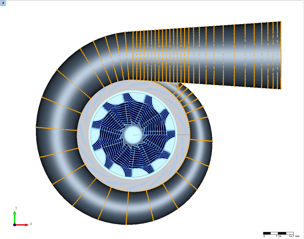
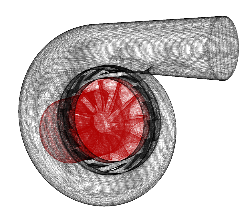
The Mesh
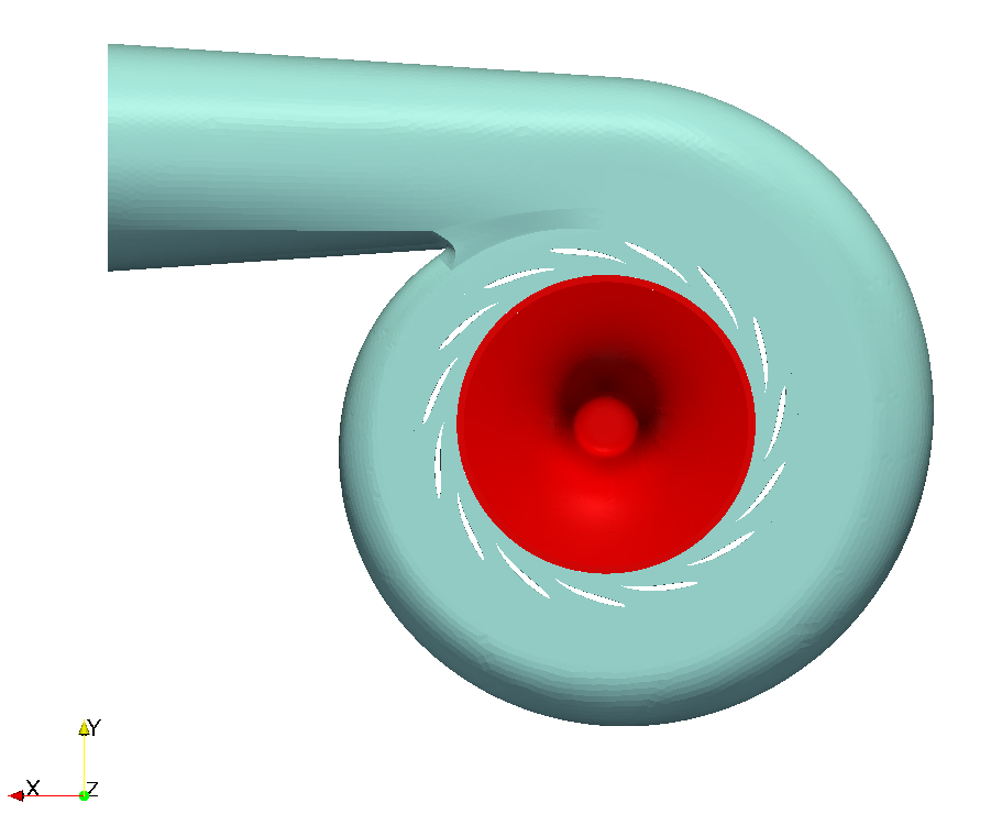
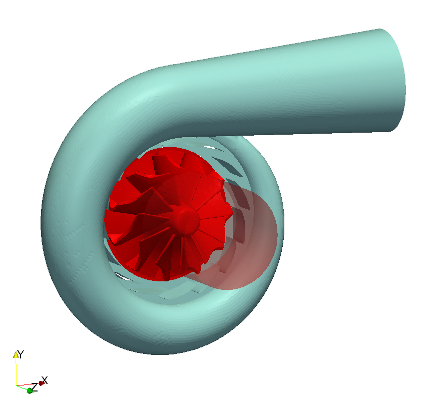
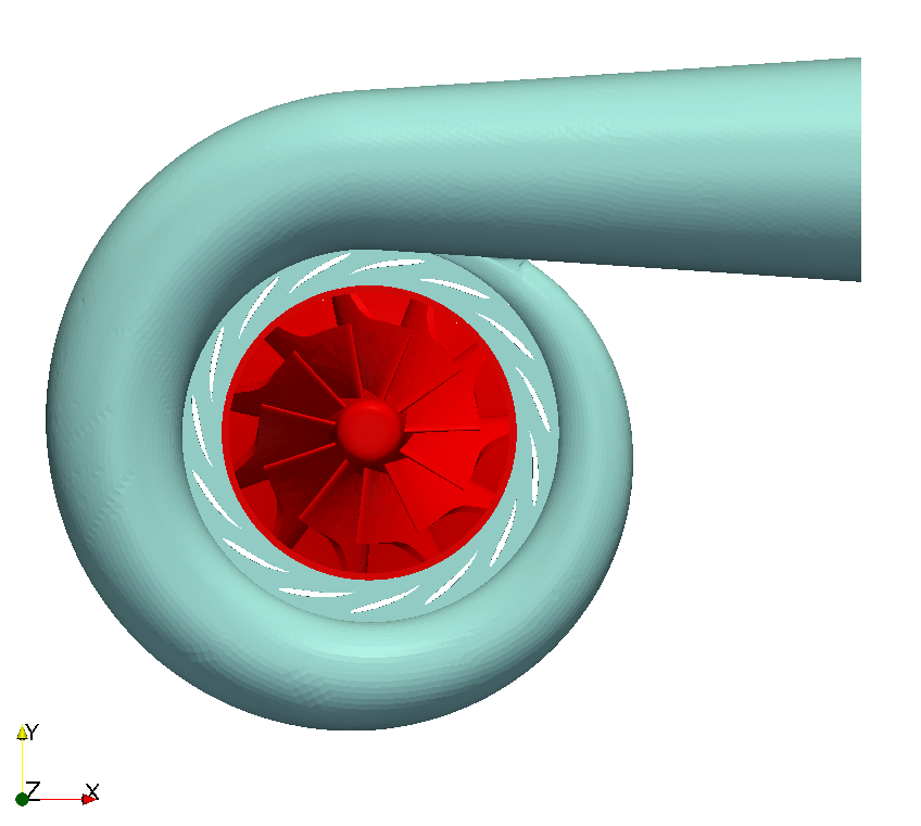
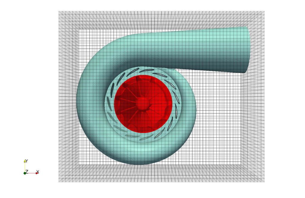
In this particular case the radial turbine model is split into four components. The Inlet tube, the Impeller, the Guide vane and the Volute. Each component has its own mesh. All the meshes are created automatically for each component within snappyHexMesh. Any number of model components is allowed.
Periodic segment or not?
The computational mesh can be created for whole impeller as well as for single blade periodic segment of the impeller. Periodic segment approach can save reasonable amount of the mesh cells, which is resulting in reduction of simulation CPU time. The full impeller approch is more robust and also allows the transient simulation on the same mesh.
Mesh Boundary Layer or not?
Another decision to take is to add “boundary layer” or not. Boundary layer is several layers of cells close to the walls to catch the velocity boundary layer. Boundary layer in the mesh usually gives more accurate results, but is paid by higher CPU time. By the experience the mesh with no boundary layer typically over-predicts the total efficiency in the order of 1% – and saves about 40% of CPU time.
Fine Mesh?
In any CFD simulation, there is always big question how fine mesh is needed for ceratin level of CFD results. In rotating machinery there is usually clear trend observed: the finer mesh leads to slightly higher efficiency.
Easy to test the mesh sensitivity
In practise the rough mesh with no boundary layer (CPU time: 4 core*hours/single point) can give the same results as the fine mesh with boundary layer (CPU time: 20 core*hour/point). So finally, the rough mesh effect can eliminate the lack of boudary layer. Anyway, with fully automated workflow it is easy to make many tests to callibrate to actual machine.
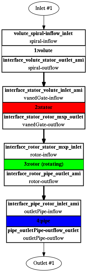
The component graph
Any project simulated in TCFD has its component graph. The component graph shows how the components are organized – the model topology. What is the inlet, the outlet and how the components are connected via interfaces.
Compressible flow model
Steady-state flow model
Medium: Air
BEP Pressure ratio: ΔpTot = 1.9 [-]
Temperature at inlet: T = 1000 [ºC]
Viscosity: μ = 1.831e-5 [Pa.s]
Rotation speed: 150000 [RPM]
BEP Mass Flow Rate: 0.045 [kg/s]
Interface: mixingInterface (radial averaging)
Turbulence Model: k-ω SST
Mesh: snappyHexMesh, hexadominant
Mesh Cells: 512436
Mesh Average y+ (full/segment): 55 [-]
CPU time (per point): 3.8 [core.hours]
For more details of CFD Simulation Set-up see TCFD Manual.
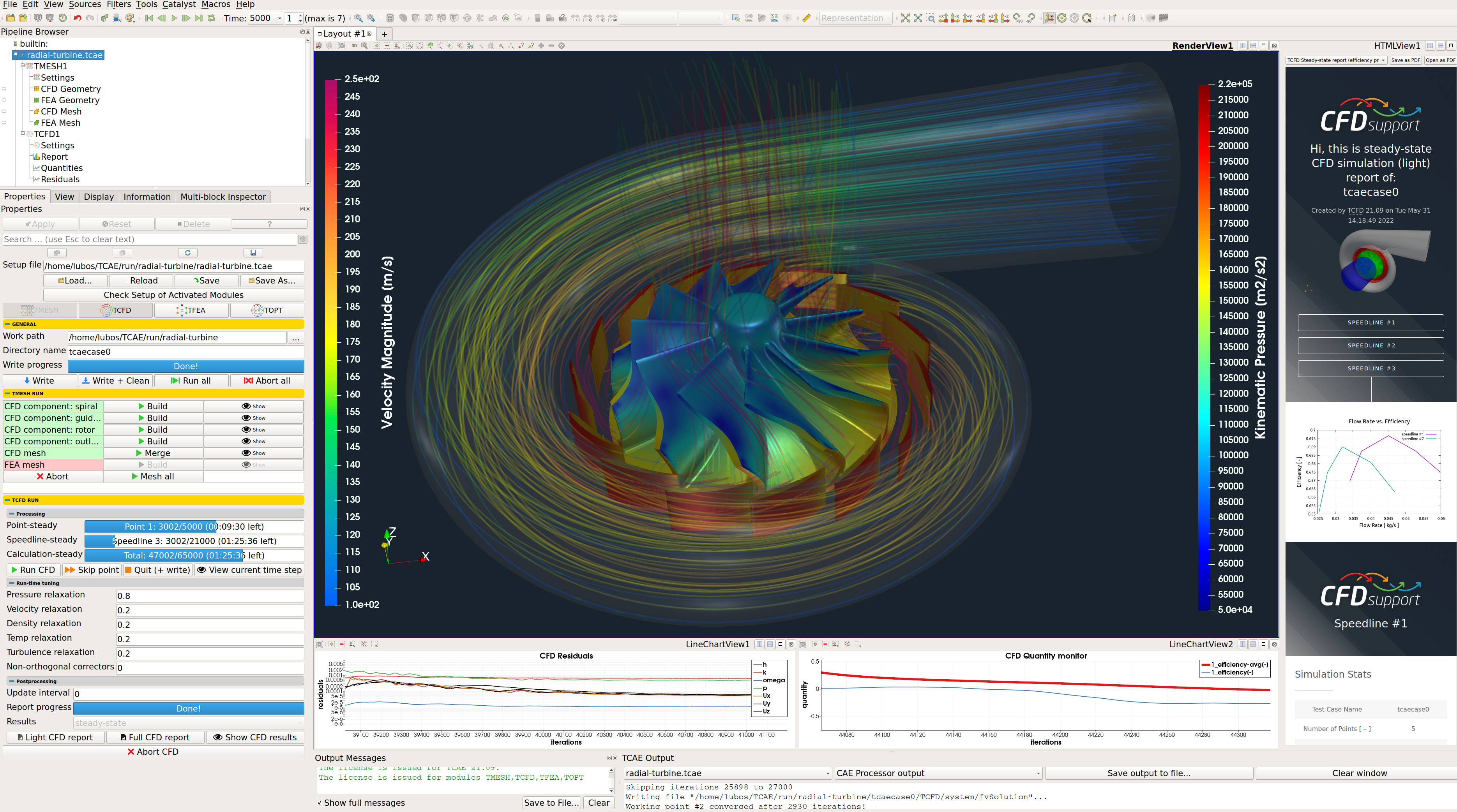
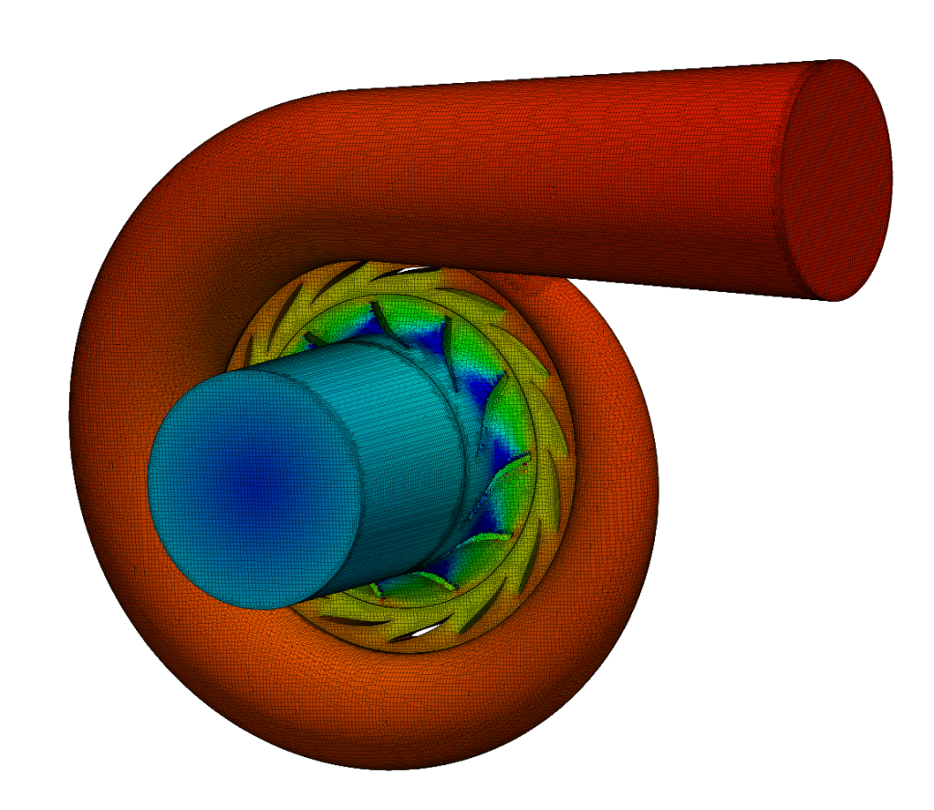
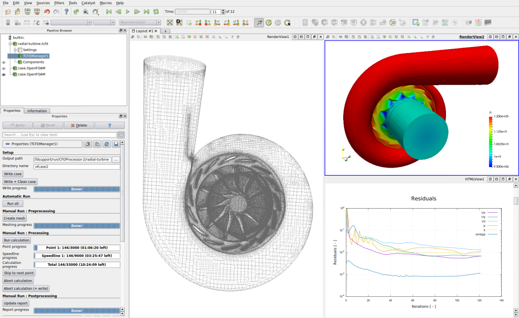
Running CFD Simulation
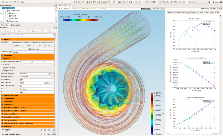
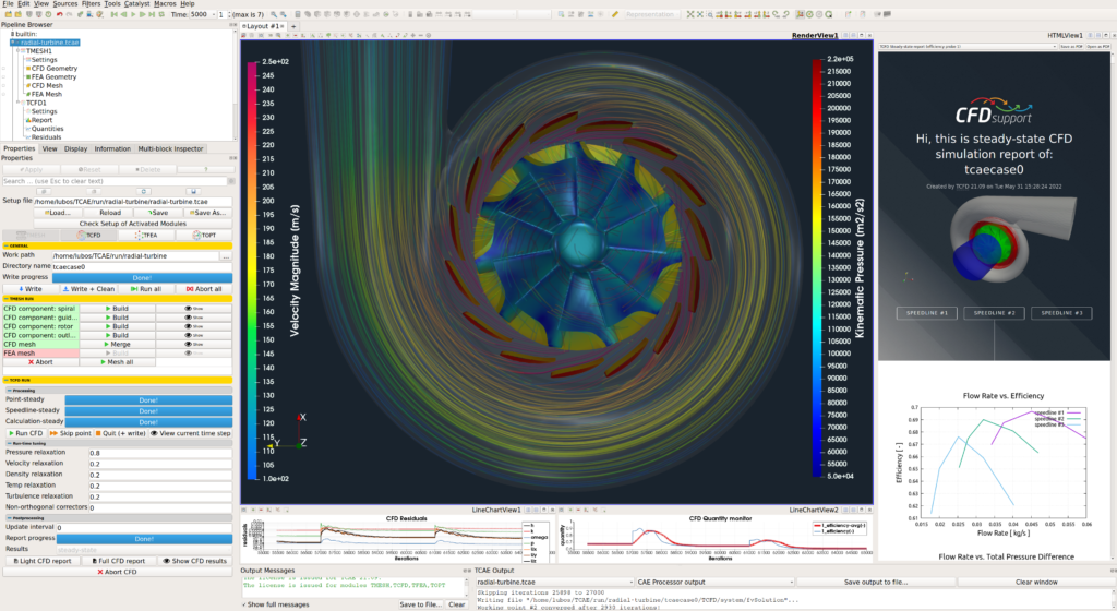
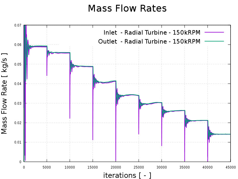
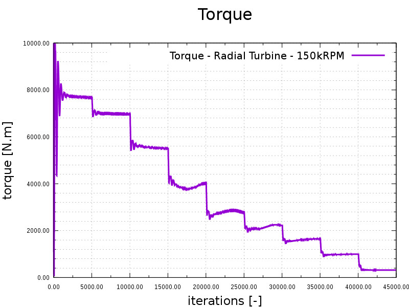
The simulation can be run using any number of parallel processors. Immediately after the simulation is started the user can follow the progress of all the important quantities: flow rates, residuals, efficiency, torque, flow number, pressure number or pressure difference. This run-time functions give the user valuable information of the convergence and also the availability to stop the simulation before its standard end.
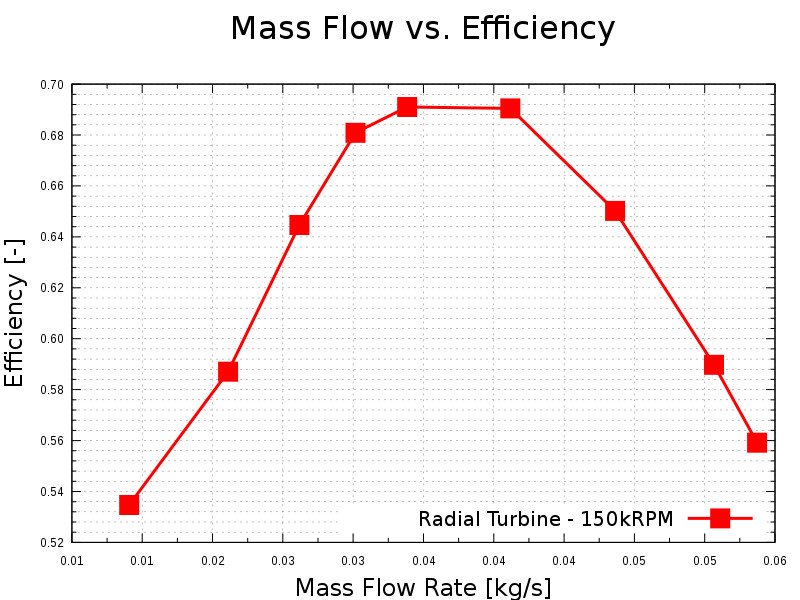
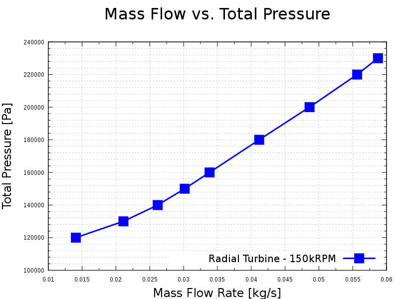
The workflow computes complete characteristics point by point.
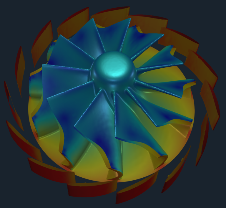
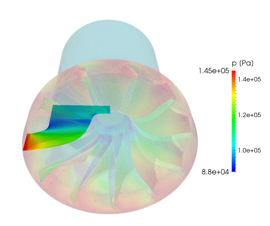
The simulation results are examined in ParaView (included in any of OpenFOAM distributions). ParaView is CFD postprocessing tool providing all standard features for analyzing CFD data.
CFD Support developed special extension to ParaView for postprocessing rotating machinery: Turbo Blade Post which is special set of filters for ParaView to enable for example blade-to-blade view, or meridional average. Turbo Blade Post detailed manual is available on-line: Turbo Blade Post Manual
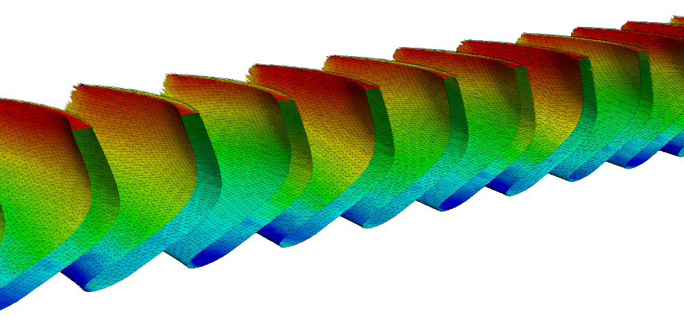
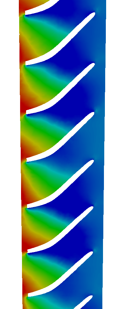
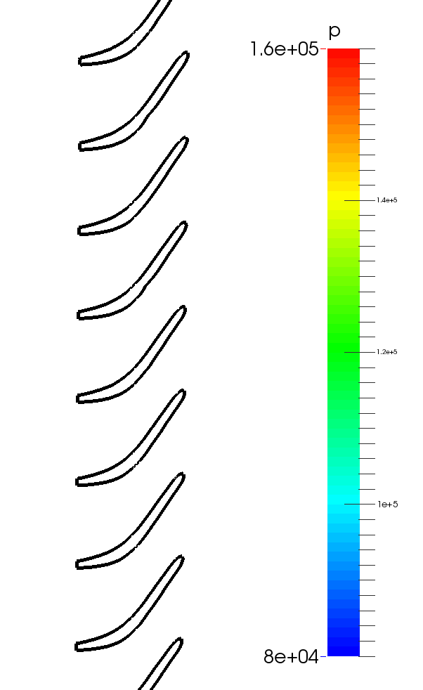
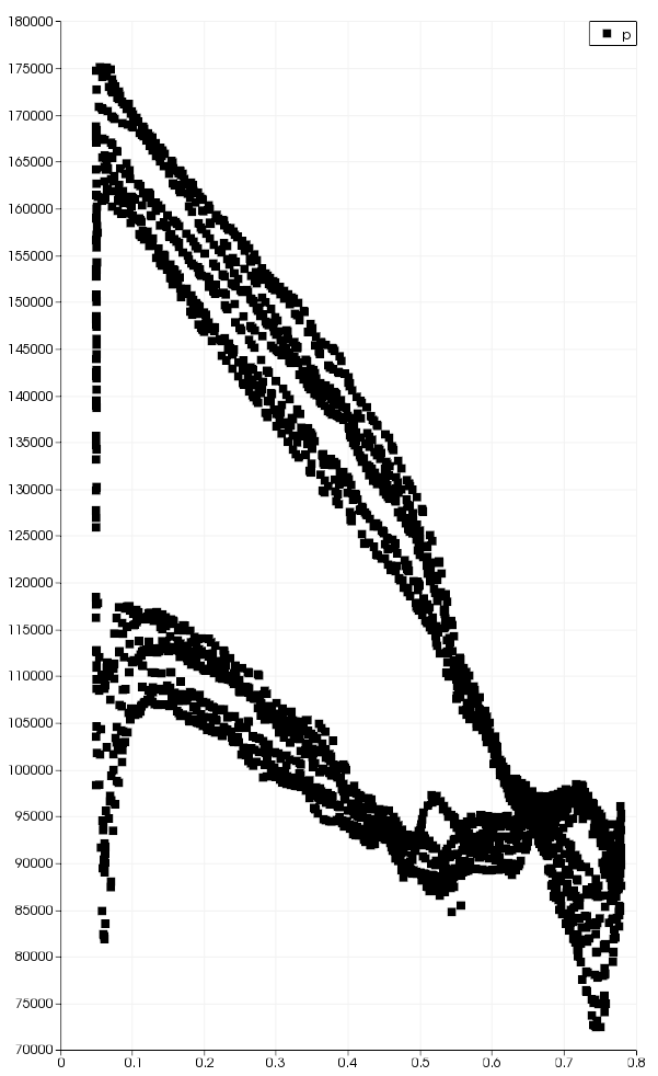
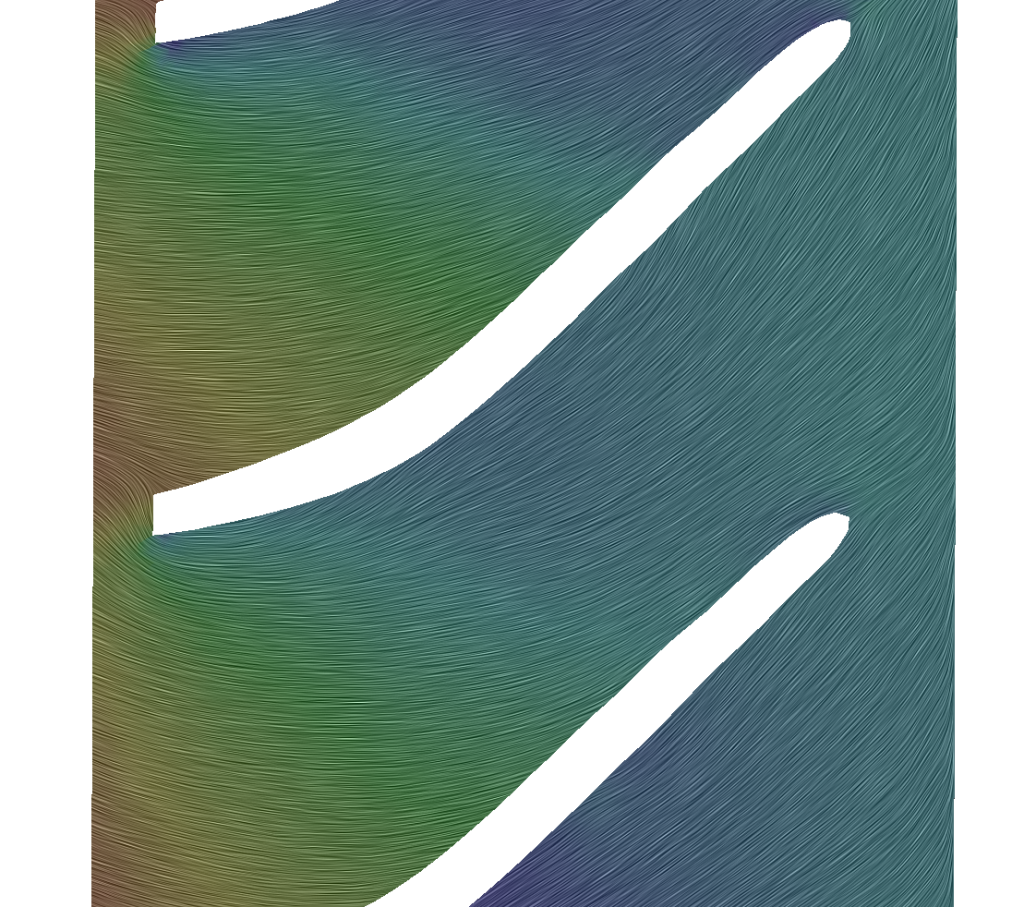
Within Turbo Blade Post the impeller mesh can be unwrapped to be able to slice the computed quantities of the same height along the blade. With such a unwrapped mesh it is also possible to plot quantities around the blade at the certain height.
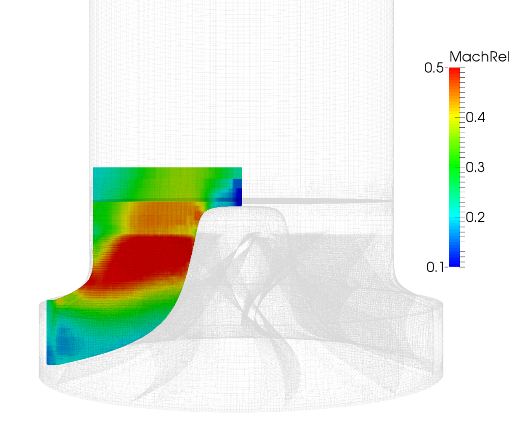
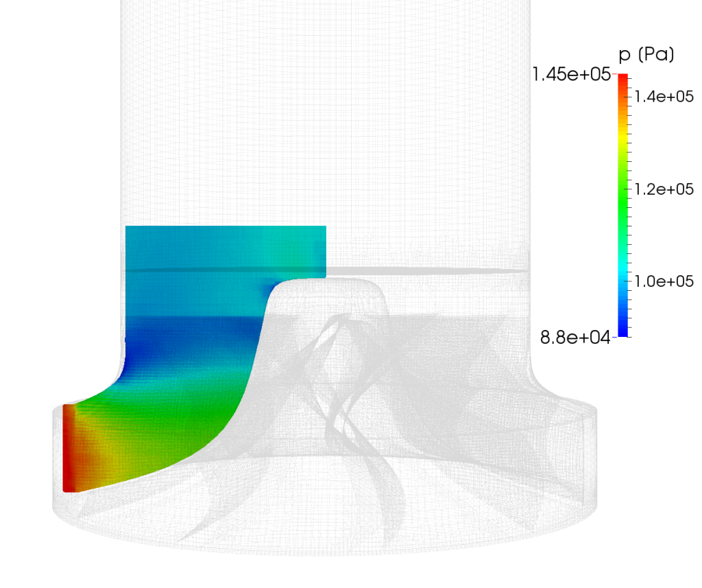
Another Turbo Blade Post function is Meridional Average which creates a meridional plane of circumferential averages of simulated quantities.