Cyclone Separator
A cyclone separator is a device typically used for removing solid particles from a liquid without the need for traditional filtration elements.
Separation is driven by a combination of swirling flow and gravity: the rotational motion creates a strong centrifugal field that pushes heavier particles toward the outer wall, while gravity guides them downward to the collection zone.
PDF Report
CFD Simulation Report
Geometry Description
Particular geometry designs depends for example on a typical particle size, particle density or on the properties of the carrier fluid.
A schematic sketch of the geometry is provided, along with the nomenclature and the specific cyclone dimensions used in this tutorial case.
| Nomenclature | Name | [mm] |
|---|---|---|
| cyclone cone tip diameter | 400 | |
| Db | cyclone body diameter | 800 |
| Dx | cyclone vortex finder diameter (outer) | 360 |
| Do | cyclone vortex finder diameter (inner) | 300 |
| Hs | solid discharge height | 500 |
| Hc | cyclone cone height | 1000 |
| Hb | cyclone body height | 1000 |
| Hv | vortex finder height | 400 |
| Ho | outlet tube height | 1000 |
| Ih | inlet height | 350 |
| Iw | inlet width | 150 |
| Id | inlet length | 1000 |
Furthermore, a step-by-step guide to the complete
preprocessing workflow in SALOME is available in the
Cyclone Separator Preprocessing Training Tutorial.
CFD Preprocessing
The geometry model must satisfy the standard CFD pre-processing requirements: it must be closed and fully watertight, free of overlaps or gaps.
Presented case is based on a single component, which contains three boundary patches — inlet, wall and outlet — representing the essential flow interfaces of the model.
The inlet serves as the location where the flow rate and particle injection conditions are supposed, while a constant pressure will be maintained at the outlet.
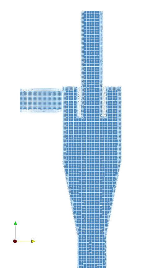
CFD Meshing

Mesh Quality Checks
To ensure numerical stability and reliable flow predictions, the mesh is evaluated using standard quality criteria as for example non-orthogonality or skewness. (Mesh quality controls)
During the mesh generation, the quality measurement is performed and quality parameters are evaluated.
If mesh quality parameters exceeds the defined thresholds the algorithm try to re-apply the offending changes in the next iteration loop.
Nevertheless, it may happen that not all violation are fixed. Therefore, it is very important to analyze the quality of the final mesh. (Mesh quality check)
The meshing process begins with an automatic detection of the internal point, ensuring that the mesher correctly identifies the fluid region enclosed by the watertight geometry.
A combination of Cartesian background grid and SnappyHexMesh refinement is used.
Using two prism layers with an expansion ratio of 1.2 and a final layer thickness of 0.25 helps maintain a smooth transition from the wall region to the core mesh.
CFD Simulation Setup
Solved first in steady state and subsequently in transient mode.
The steady-state solution serves as the initial condition for the transient simulation, providing a converged and physically consistent flow field from which unsteady behaviour can evolve.
The transient simulation employs an adaptive time-stepping strategy, with the Courant number limited to Co = 5, ensuring numerical stability while maintaining computational efficiency.
The working fluid is air, treated as incompressible with a dynamic viscosity of 1.8×10⁻⁵ Pa·s, a density of 1.2 kg/m³, and a reference pressure of 1 atm. Gravity is included as a constant body force with an acceleration of 9.81 m/s² against the direction of z axis. Turbulence is resolved using the k–ω SST model in combination with appropriate wall functions,
General
Fluid
Particles
- TCAE Simulation type: stator
- Number of components: 1 [-]
- Speedlines: 1 [-]
- Simulation points: 1 [-]
- Wall roughness: none
- Steady state + transient
- Time step: adaptive
- Physical model: Incompressible
- Turbulence: k-ω-SST
- Wall treatment: Wall functions
- Fluid: Air
- Inlet: 500 [l/s]
- Outlet: Fixed Pressure 0 [m2/s²]
- Gravity
- Lagragian approach
- Forces: Drag + gravity
- Injection: Inlet patch
- Particle inlet velocity: (0 10 0) m/s
- Particle density: 2000 kg/m³
- Wall treatment: Rebound condition (e=0.7, μ=0.1)
- Particle size: 5mm
- Number of particles: 2000
In this tutorial, we consider only a single class of particles with uniform density. Each particle is tracked in detail: how it accelerates, how it interacts with the swirling flow, how it bounces off the walls with controlled energy loss (e = 0.7, μ = 0.1). The rebound condition represents a generally inelastic collision between a particle and a walls, where the degree of inelasticity can be controlled by two parameters: e (the normal restitution coefficient) and μ (represents the tangential friction)
To quantify these interactions, the patchCollisionDensity function object generates fields showing the number and rate of collisions per unit area on all patches. Furthermore, a minimum-speed threshold can be applied to filter out slow, non-meaningful contacts, ensuring that only physically relevant collisions are included in the analysis.
Postprocessing

Download TCAE Tutorial - Cyclone Separator
File name: Cyclone-Separatot-TCAE-Tutorial.zip
File size: 1.9 MB
Tutorial Features: CFD, TCAE, TMESH, TCFD, SIMULATION, INCOMPRESSIBLE FLOW, AUTOMATION, WORKFLOW, SNAPPYHEXMESH, Particles, 3D, Finite Volume, CFD, SnappyHexMesh,TCAE environment, OpenFOAM, k-ω-SST