This centrifugal pump is an artificial test case (inspired by the real past project) to demonstrate the capabilities of the new Non-Conformal Coupling (NCC) interface functionality.
This test case highlights the flexibility of mapping interface conditions, supporting transient simulation with a partial overlap interface.
From TCAE 26.03 on, the interface interpolation AMI (Arbitrary Mesh Interface) method is completely replaced by NCC (Non-Conformal Coupling). NCC calculates the actual geometric intersection of the mesh faces.
Benefits: Stability. Wider range of applications. It ensures a “strictly conservative” transfer of fluxes (mass, momentum, energy) across the interface. It is more realistic, robust, reduces numerical errors, and allows for much more flexible mesh configurations where surfaces only partially touch.
Geometry Description & CFD Preprocessing
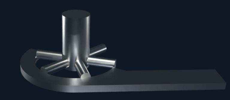
The geometry is inspired by a centrifugal pump layout, providing a realistic engineering context.
However, it is not intended to represent a conventional pump design. Instead, it was purpose-built to demonstrate the newly introduced functionality – NCC (Non-Conformal Coupling) – implemented as a mapping interface condition type.
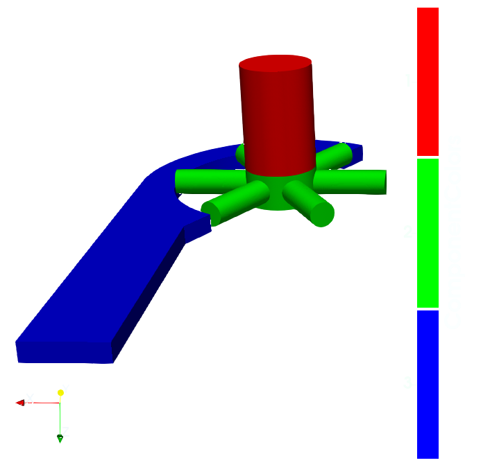
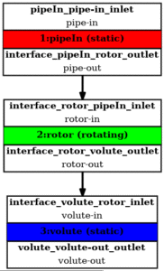
Within the preprocessing workflow, a strictly modular structure is maintained. The model is decomposed into three primary components, each defined as an independent domain with its own boundary patches.
This decomposition enables independent mesh generation for each component while allowing flexible coupling through interface mapping during the simulation.
Component 1 represents the pipe region and includes the inlet, wall and interface.
Component 2 represents the rotor. It includes wall boundary defining the rotating surface and two interface patches that enable coupling with the neighboring stationary domains.
Component3 represents the volute casing and consist of outlet, wall and interface.
CFD Meshing
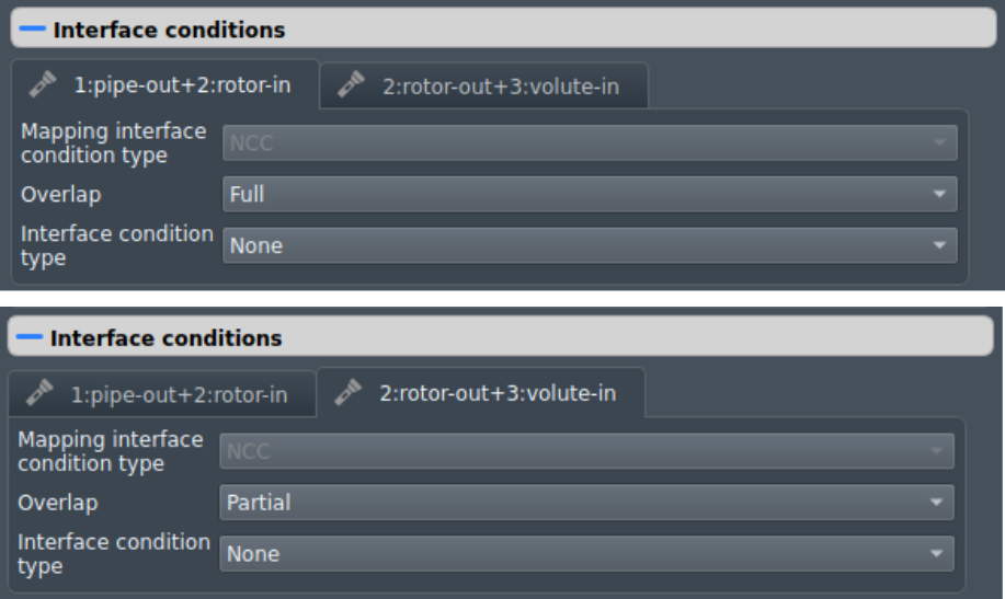
The interface coupling between the domains is handled through the Non-Conformal Coupling (NCC) approach. Within the interface condition settings, the user specifies the overlap configuration (Full or Partial) and optionally the interface condition type, where additional conditions such as a pressure jump can be defined.
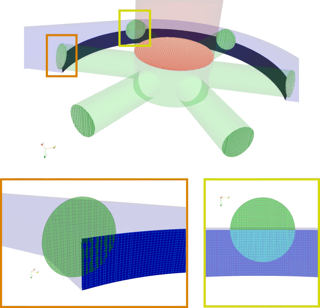
The mesh configuration in this demonstration test case was intentionally designed to demonstrate both full overlap and partial overlap interface configurations.
Detail of interface mesh.
In the full overlap configuration, the interface surfaces completely coincide, allowing the entire interface area to participate in the coupling.
In contrast, the partial overlap configuration represents cases where only a portion of the interface surfaces intersect. In such situations, the solver automatically detects the overlapping regions and constructs the interface mapping only for the intersecting areas.
The highlighted regions in the figure illustrate examples of both full and partial interface overlaps.
CFD Simulation Setup
TCAE Simulation type: pump
Number of components: 3 [-]
Speedlines: 1 [-]
Simulation points: 1 [-]
Wall roughness: none
Turbulence: k-ω-SST
Wall treatment: Wall functions
Time management: Steady+Transient
Time step: constant, 0.5°
Dynamic Mesh
Physical run-time: 2 revolutions
Physical model: Incompressible
Fluid: Water
Rotational speed: 300 RPM
Inlet: Fixed Pressure 82050 [m2/s²]
Outlet: Fixed Pressure 101325 [m2/s²]
Interface condition
Mapping interface condition type: NCC
Overlap pipe/rotor: Full
Overlap rotor/volute: Partial
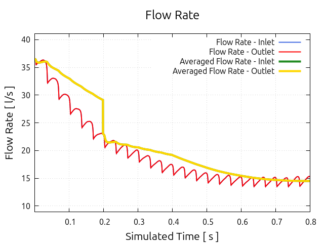
The simulation is driven by a prescribed pressure difference between the inlet and outlet, resulting in a volumetric flow rate of approximately 15 l/s through the system.
Instead of directly prescribing the volumetric flow rate, a pressure-driven setup was chosen. This approach provides a more physically consistent solution for this configuration and leads to a smoother pressure distribution across the domains.
Interface Coupling Performance
The coupling between the individual domains is handled using Non-Conformal Coupling (NCC), which replaces the previous Arbitrary Mesh Interface (AMI) approach.
The transition to NCC was motivated by the need for a more flexible and robust interface treatment. Unlike AMI, which requires well-defined overlapping interface surfaces, NCC allows coupling even when the interface patches only partially overlap. The solver automatically detects the intersecting regions and constructs the mapping used for flux exchange between the domains.
Unlike the previous AMI approach, which relied primarily on interpolation, NCC constructs the coupling based on the geometric intersection of interface faces, ensuring a strictly conservative transfer of fluxes across the interface. Compared to AMI, the method improves the transfer of fluxes across the interface and avoids numerical issues associated with interpolation between mismatching mesh faces. This ensures a strictly conservative transfer of fluxes across the interface and provides a more robust treatment of non-conformal mesh interfaces. [1]
Consequently, NCC simplifies the handling of independently generated meshes and supports more flexible interface configurations. This makes it particularly suitable for multi-region simulations such as rotating machinery, where mesh regions may move relative to each other or only partially overlap.
Results
(2D) Streamlines Colored by Velocity Magnitude in the z = 0.25 Plane
(3D) Streamlines Colored by Velocity Magnitude with rotor cross-section in z = 0.25 Plane