CFD SUPPORT introduces the new generation of CFD simulations. TCFD brings an extreme increase of productivity to CFD simulations. TCFD is extremely popular project, because it successfully merged benefits of an open-source (perpetual, unlimited users, jobs, and cores, customizable, …) with benefits of commercial codes (professional support, well tested, ready for the industry, robust, accurate, automated, GUI, …).
TCFD is fully automated, it can run the whole workflow by a single command: data input, new case is written down, mesh is created, case is set-up, case is simulated, results are evaluated and the results report is written down. Both GUI and batch mode. Data in – data out. TCFD is mainly focused on supporting the engineers in their real value added work. TCFD is fully automated and the beauty of TCFD is that it is the user who decides how deep to dive into a CFD or not at all. And all the options remain open at the same time.
Water Valve
A valve is a device that regulates, directs or controls the flow of a fluid (gases, liquids, fluidized solids, or slurries) by opening, closing, or partially obstructing various passageways. Valves are technically fittings, but are usually discussed as a separate category. In an open valve, fluid flows in a direction from higher pressure to lower pressure. The word is derived from the Latin valva, the moving part of a door, in turn from volvere, to turn, roll. The simplest, and very ancient, valve is simply a freely hinged flap which drops to obstruct fluid (gas or liquid) flow in one direction, but is pushed open by flow in the opposite direction. This is called a check valve, as it prevents or “checks” the flow in one direction. Modern control valves may regulate pressure or flow downstream and operate on sophisticated automation systems.
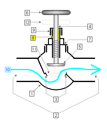
Cross-sectional diagram of an open globe valve. 1. body 2. ports 3. seat 4. stem 5. disc when valve is open 6. handle or handwheel when valve is open 7. bonnet 8. packing 9. gland nut 10. fluid flow when valve is open 11. position of disc if valve were shut 12. position of handle or handwheel if valve were shut
Preprocessing
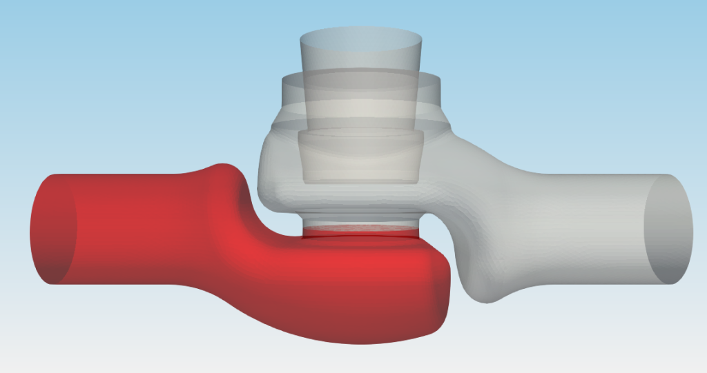
We started with a CAD model of Valve in file format STEP. For a professional CFD simulation, the original STEP file is usually too complex and therefore certain preprocessing work has to be done. Using an open-source software Salome, the model is simplified and cleaned. The final surface model is made waterproof. Finally, 2D surface meshes are generated to fit the CAD surface (wet surface) in an acceptable way. Individual STL files, that define the wet surfaces of the valve are exported. Remember, the preprocessing is extremely important for each CFD workflow. Preprocessing always limits the CFD results and sets the expectations.
Input data
The surface model data in .stl file format together with physical inputs are loaded in TCFD. Other option would be loading an external mesh in OpenFOAM® mesh format, or loading an MSH mesh format (Fluent mesh format). This CFD methodology employs a multi component approach, which means the model is split into a certain number of regions. In TCFD each region can have its own mesh and individual meshes comunicate via interfaces.
Grapgical interface
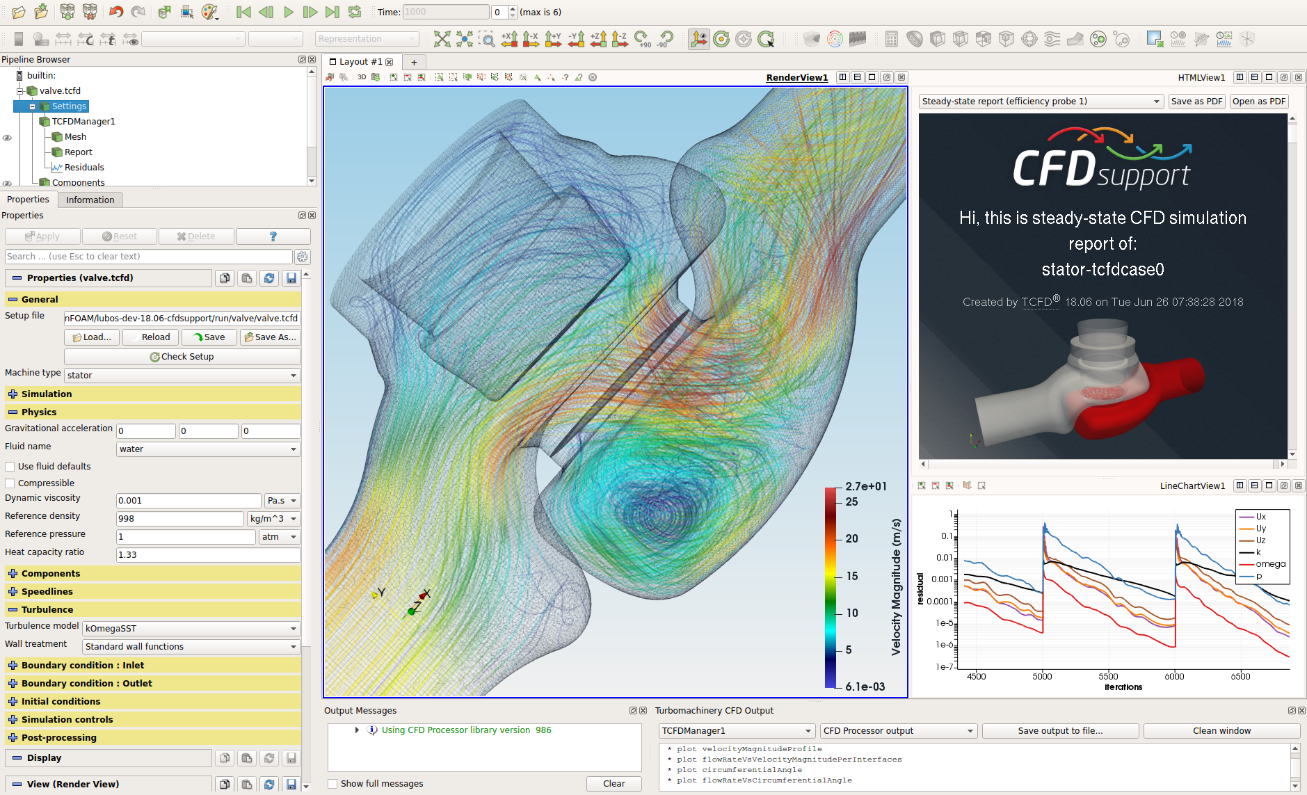
All the case settings are set in a graphical intergace. The TCFD graphical interface is based on ParaView. Most of the users prefer to use a graphical interface for case setup and then decide for example to use the command line for cluster run. The workflow is very flexible and the command line vs GUI decision is always on the user.
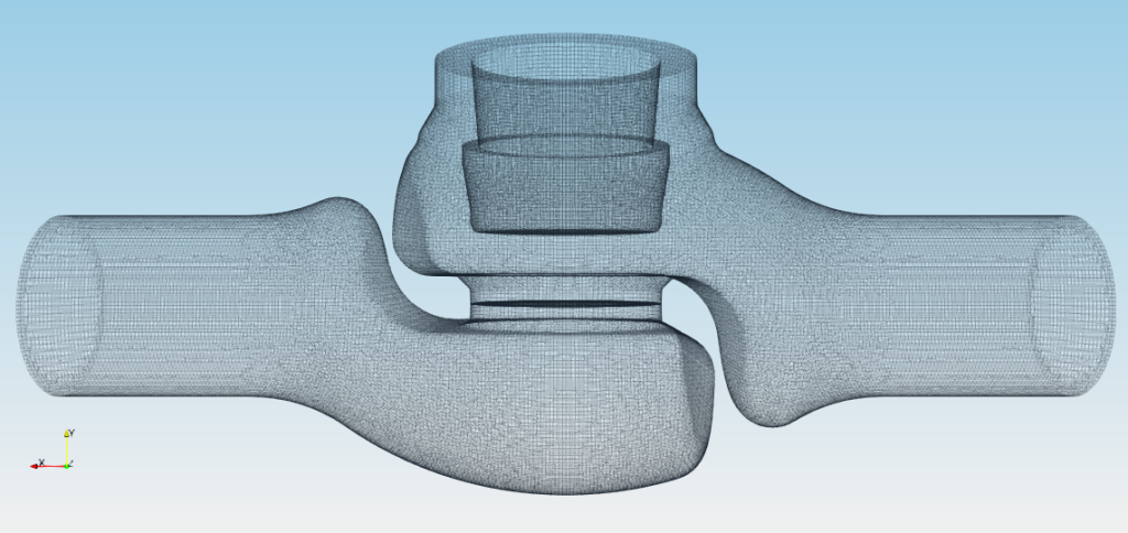
Mesh
In this particular case, the simulation model is split into two components. Each component has its own mesh. All the meshes are created automatically for each component within snappyHexMesh. Any number of model components is allowed.
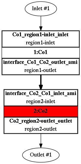
The component graph
Any project simulated in TCFD has its component graph. The component graph shows how the components are organized – the model topology. What is the inlet, the outlet and how the components are connected via interfaces.
CFD Simulation Set-up
Incompressible flow model
Steady-state flow model
Medium: Water
Viscosity: ν = 8.899e-7 [m2/s]
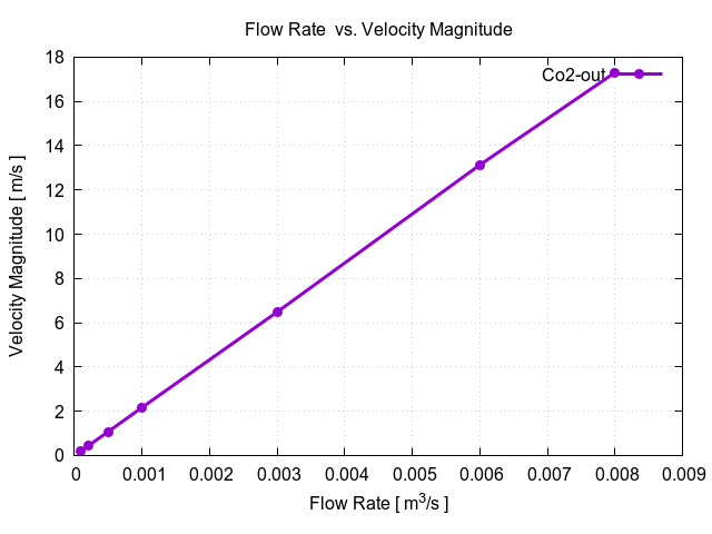
Flow Rate: 1 [l/s]
Interface: AMI
Turbulence Model: k-ω SST
Mesh: snappyHexMesh
Mesh Cells: 268,752
Mesh Average y+ : 130.45 [-]
CPU time (steady-state): 0.65 [core.hours]
For more details of CFD Simulation Set-up see TCFD Manual.
Running CFD Simulation
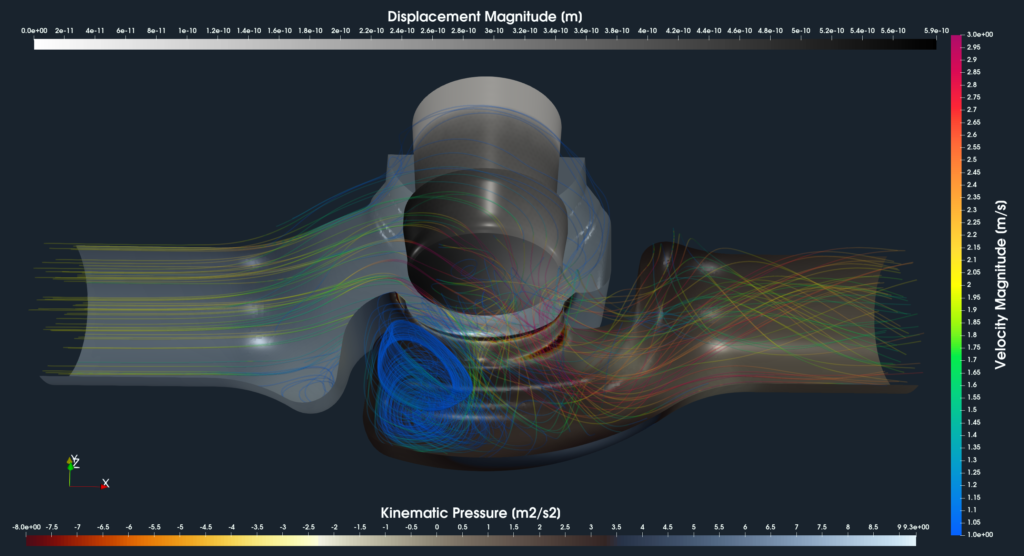
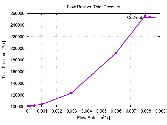
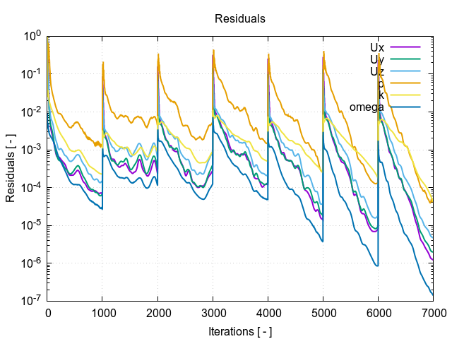
The simulation can be run on any number of parallel processors. Immediately after the simulation is started, the user can follow the progress of all the important quantities in a HTML report: flow rates, residuals, efficiency, torque, pressure difference and many others. These run-time functions give the user valuable information of the simulation convergence and also the availability to stop the simulation before its expected end.
Every simulation performed in TCFD has its report in web responsive .html and pdf format: Valve – Results Report.