Previous: Creating the Inlet Part Up: SALOME example – Cyclone Next: Split Each Part to
This is an automatically generated documentation by LaTeX2HTML utility. In case of any issue, please, contact us at info@cfdsupport.com.
Splitting Each Part to Perfect Fit - Inlet-extrusion
To achieve a perfect connection between the Inlet-extrusion and the Cyclone-rotPart a small modification has to be done. Let’s start with the Inlet-extrusion.
- At first the Inlet-extrusion will be split.
- Navigate to the menu Operations > Partition and set the following entries (see Fig.
 ):
):- Rename parameter Name to Inlet-body-part.
- Set Objects to Inlet-extrusion.
- Set Tool Objects to Cyclone-rotPart.
- Resulting type is Shell.
- Click Apply and Close.

Figure: Inlet-extrusion partitioning.
- Afterwards, the new Shell contains only the outer parts of Inlet-body-part will be created.
- At first, the new Faces from the Inlet-body-part are created.
- Navigate to the menu New Entity > Explode and do the following steps (see Fig.
 ):
):- Set Main Object to Inlet-body-part.
- Check the Select Sub-Shapes option.
- By holding the Shift key on your keyboard and clicking on desired parts, i.e. 4 faces which are not inside the Cyclone-rotPart.
- Click Apply and Close.

Figure: Creating the new faces byExplode Tool.
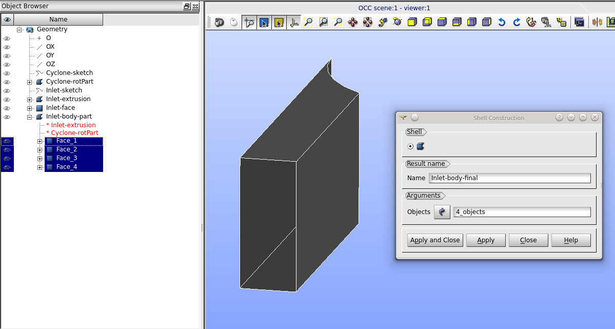
- Finally, the new shell is created using those faces from the previous step.
- Navigate to the menu New Entity > Build > Shell and follow these steps (see Fig.
 ):
):- Rename Name to Inlet-body-final.
- In the Objects select those faces mentioned in the previous step. Click them (holding Shift key) in the viewer.
- The other way to that is to select these faces in the Object Browser by clicking and holding Ctrl key.
- Click Apply and Close.

Figure: Creating a new Shell.


