1

Previous: The Allrun script Up: Test case: Propeller Next: Results

This is an automatically generated documentation by LaTeX2HTML utility. In case of any issue, please, contact us at info@cfdsupport.com.

The initialization script Allrun.pre

#!/bin/sh
cd ${0%/*} || exit 1    # Run from this directory

# Source tutorial run functions
. $WM_PROJECT_DIR/bin/tools/RunFunctions

# copy propeller surface from resources directory
cp $FOAM_TUTORIALS/resources/geometry/propellerTip.obj.gz constant/triSurface/


# - meshing

runApplication blockMesh

runApplication surfaceFeatureExtract

runApplication snappyHexMesh -overwrite

runApplication renumberMesh -overwrite

# force removal of fields generated by snappy
rm -rf 0

# - generate face/cell sets and zones
runApplication topoSet -dict system/createInletOutletSets.topoSetDict

# - create the inlet/outlet and AMI patches
runApplication createPatch -overwrite

# - test by running moveDynamicMes
#runApplication moveDynamicMesh -checkAMI

# - set the initial fields
cp -rf 0.orig 0
  • We start the same way as in the script Allrun; we set the working directory and introduce the auxiliary functions.
  • Line 8 copy the stem surface model data from file
    $FOAM_TUTORIALS/resources/geometry/propellerTip.obj.gz. Data for the other geometry parts are already in the directory propeller/constant/triSurface
    NOTE: No copy is needed. The *.obj file is already in tutorial directory
  • Line 13: We use the application blockMesh and make the basic computational mesh, the standard output is forwarded into the log file log.BlockMesh
  • Line 15: We run surfaceFeatureExtract for the *.obj files defined in system/surfaceFeatureExtractDict and save the output into the log files.
  • Utility surfaceFeatureExtract extracts edge information from .obj files and saves it as an .eMesh file. These files are used by the utility snappyHexMesh, which often has problems with rounding the edges. The switch -includedAngle 150 sets the maximal angle between two patches to be considered an edge to 111 and the switch -minElem 10 sets the minimal edge length (number of elements on the edge). These switches are defined in file system/surfaceFeatureExtractDictDefaults .
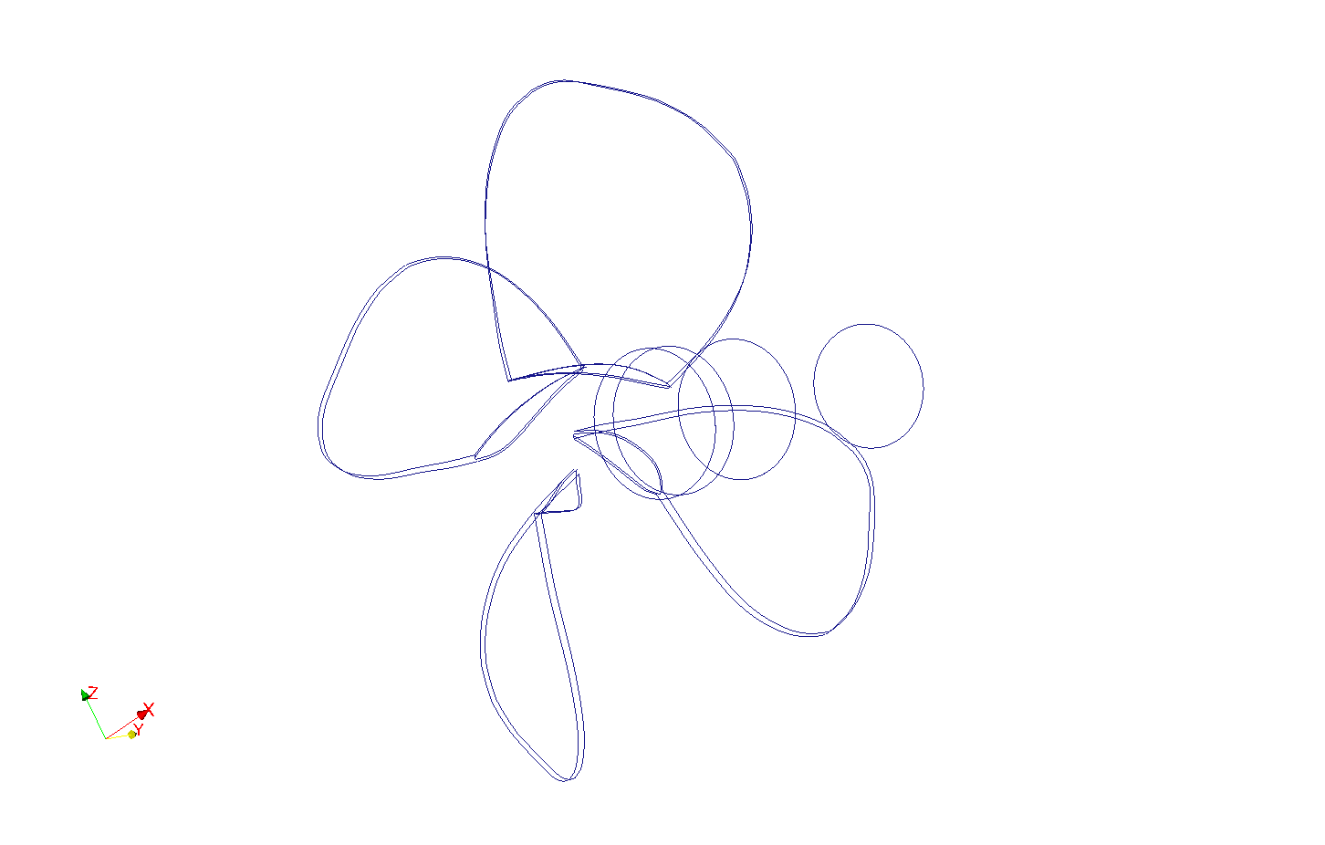
  • Paraview cannot visualize the .eMesh files but we can convert them using the utility surfaceFeatureConvert to another format and visualize them, see figure crossref 2
    # surfaceFeatureConvert propellerTip.eMesh propellerTip.eMesh.obj

    # paraview - -data='propellerTip.eMesh.obj'

eMesh

Figure: The outcome after using surfaceFeatureConvert utility

  • Line 17: We launch the mesh making process using the snappyHexMesh utility. Besides other patches, innerCylinderSmall patch and innerCylinderSmall_slave patch are defined. Later these patches will be used for the AMI interface. The switch -overwrite disables creation of multiple folders containing the gradually refined mesh. Everything is saved into the folder constant/polyMesh, which means that also the mesh created with blockMesh is lost. Here is the part of code from snappyHexMeshDict , that gives rise to innerCylinderSmall_slave patch.


     refinementSurfaces
        {
            innerCylinderSmall
            {
                level       (4 4);
    
                faceType    boundary;
                cellZone    innerCylinderSmall;
                faceZone    innerCylinderSmall;
                cellZoneInside  inside;
            }


  • Line 19: We use renumberMesh to improve numbering of our mesh. It causes better property of matrixes which perform in the following numerical computation.
  • NOTE: The backslash before some bash command, applied on line 22, does not expand aliases
  • Line 25: Utility topoSet is used for mesh topology modifying. We use createInletOutletSets and choose a cell zone at the inlet or outlet (these will be needed later for inlet and outlet patch creation), see
    system/createInletOutletSets.topoSetDict . Here is how outletFaces are created:


     actions
    (
        {
            name    boundaryFaces;
            type    faceSet;
            action  new;
            source  patchToFace;
            sourceInfo
            {
                name outerCylinder;
            }
        }
        
        {
            name    outletFaces;
            type    faceSet;
            action  new;
            source  faceToFace;
            sourceInfo
            {
                set boundaryFaces;
            }
        }
        
        {
            name    inletFaces;
            type    faceSet;
            action  new;
            source  faceToFace;
            sourceInfo
            {
                set boundaryFaces;
            }
        }
        
        {
            name    outletFaces;
            type    faceSet;
            action  subset;
            source  normalToFace;
            sourceInfo
            {
                normal  (0 -1 0);   // Vector
                cos     0.3;        // Tolerance (max cos of angle)
            }
        }
    
        ...
        
    );
    
  • Line 28: We run createPatch which sets AMI interface.
  • Line 34: We apply the initial conditions that were backed up in folder 0.org .