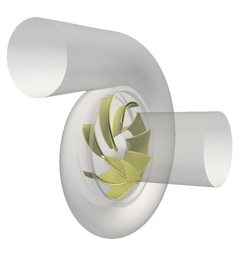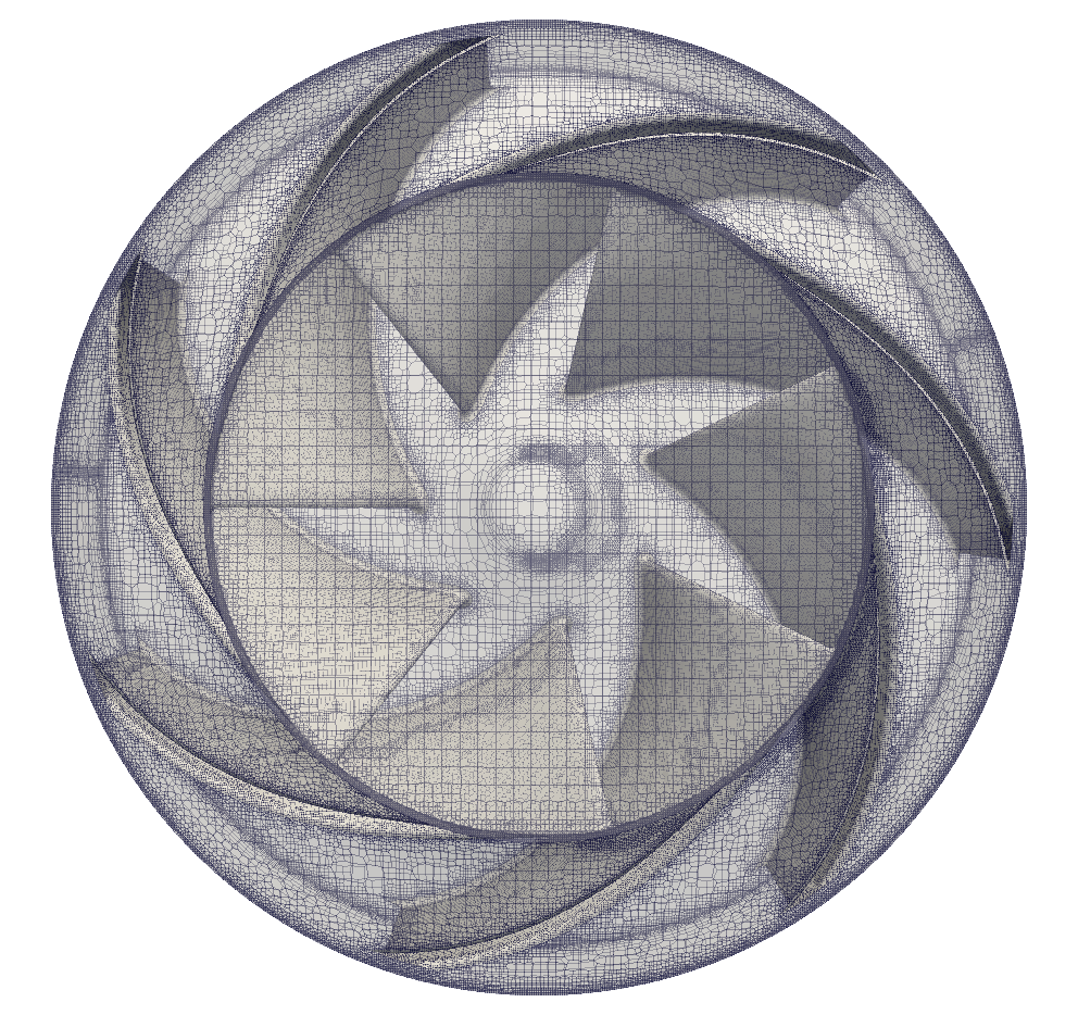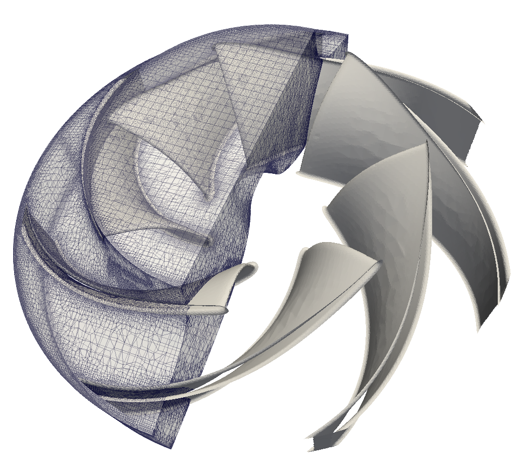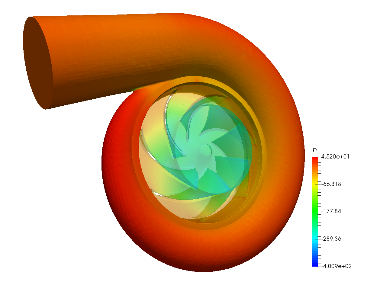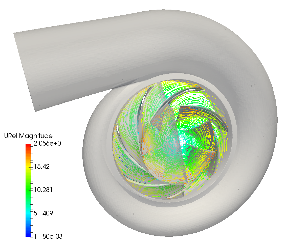


All following Turbo Blade Post usage examples are presented on a numerical results from a simulation of an incompressible flow in a pump. The boundary geometry of the simulated volume of the pump is shown in the figure ![[*]](https://www.cfdsupport.com/wp-content/uploads/2022/02/crossref.png) . The meshing and calculation has been done by TCFD / CFD Processor using the OpenFOAM package. The resulting meshes are displayed in the figures and . Numerical results are illustrated in the figures and . These are classical visualisations from ParaView. Turbo Blade Post offers several new ways how to inspect the numerical data, which are presented in the following chapters.
. The meshing and calculation has been done by TCFD / CFD Processor using the OpenFOAM package. The resulting meshes are displayed in the figures and . Numerical results are illustrated in the figures and . These are classical visualisations from ParaView. Turbo Blade Post offers several new ways how to inspect the numerical data, which are presented in the following chapters.
. The meshing and calculation has been done by TCFD / CFD Processor using the OpenFOAM package. The resulting meshes are displayed in the figures and . Numerical results are illustrated in the figures and . These are classical visualisations from ParaView. Turbo Blade Post offers several new ways how to inspect the numerical data, which are presented in the following chapters.