1

Previous: Instant convergence monitoring during Up: Test case: motorBike Next: Function probe

This is an automatically generated documentation by LaTeX2HTML utility. In case of any issue, please, contact us at info@cfdsupport.com.

Aerodynamic coefficients 90 and 91

  • Aerodynamic coefficients 90 and 91 can be evaluated by adding additional functions to controlDict file
  • Configuration file controlDict is extended:
    /*--------------------------------*- C++ -*----------------------------------*\
    | =========                 |                                                 |
    | \\      /  F ield         | OpenFOAM: The Open Source CFD Toolbox           |
    |  \\    /   O peration     | Version:  dev                                   |
    |   \\  /    A nd           | Web:      www.OpenFOAM.org                      |
    |    \\/     M anipulation  |                                                 |
    \*---------------------------------------------------------------------------*/
    FoamFile
    {
        version     2.0;
        format      ascii;
        class       dictionary;
        object      controlDict;
    }
    // * * * * * * * * * * * * * * * * * * * * * * * * * * * * * * * * * * * * * //
    
    application     simpleFoam;
    
    startFrom       latestTime;
    
    startTime       0;
    
    stopAt          endTime;
    
    endTime         500;
    
    deltaT          1;
    
    writeControl    timeStep;
    
    writeInterval   100;
    
    purgeWrite      0;
    
    writeFormat     binary;
    
    writePrecision  6;
    
    writeCompression uncompressed;
    
    timeFormat      general;
    
    timePrecision   6;
    
    runTimeModifiable true;
    
    functions
    {
        #include "streamLines"
        #include "cuttingPlane"
        #include "forceCoeffs"
    }


    // ************************************************************************* //
    
  • Object libs and includes of files streamLines and cuttingPlane can be deleted for this time. File forceCoeffs reads as follows:
    /*--------------------------------*- C++ -*----------------------------------*\
    | =========                 |                                                 |
    | \\      /  F ield         | OpenFOAM: The Open Source CFD Toolbox           |
    |  \\    /   O peration     | Version:  dev                                   |
    |   \\  /    A nd           | Web:      www.OpenFOAM.org                      |
    |    \\/     M anipulation  |                                                 |
    \*---------------------------------------------------------------------------*/
    
    forceCoeffs1
    {
        type            forceCoeffs;
    
        libs            ("libforces.so");
    
        writeControl    timeStep;
        timeInterval    1;
    
        log             yes;
    
        patches         (motorBikeGroup);
        rho             rhoInf;      // Indicates incompressible
        rhoInf          1;           // Redundant for incompressible
        liftDir         (0 0 1);
        dragDir         (1 0 0);
        CofR            (0.72 0 0);  // Axle midpoint on ground
        pitchAxis       (0 1 0);
        magUInf         20;
        lRef            1.42;        // Wheelbase length
        Aref            0.75;        // Estimated
        /*
        binData
        {
            nBin        20;          // output data into 20 bins
            direction   (1 0 0);     // bin direction
            cumulative  yes;
        }
        */
    }
    

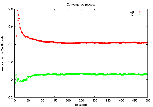
  • forceCoeffs1 computes coefficients $ C_l$ and $ C_d$ in direction liftDir and dragDir, data are saved after each time step in directory postProcessing/forceCoeffs1

  • Easy Gnuplot script named e.g. plotCdCl displays $ C_l$ and $ C_d$ development:
    # Gnuplot script file for plotting data from file "forceCoeffs.dat"
    set title "Convergence process"
    set xlabel "Iterations"
    set ylabel "Aerodynamics Coefficients"
    plot [ ][-0.2:0.8]\
          "postProcessing/forceCoeffs1/0/forceCoeffs.dat" using 1:3 title 'Cd', \
          "postProcessing/forceCoeffs1/0/forceCoeffs.dat" using 1:4 title 'Cl'
    pause mouse
    
  • Run the script:
    # gnuplot plotCdCl
openfoam tutorial motor bike cd cl

Figure: OpenFOAM tutorial motor bike. 90 and 91 development during computation

Running blockMesh

  • Each application has its help:
    # blockMesh -help
    Usage: blockMesh [OPTIONS]
    options:
      -blockTopology    write block edges and centres as .obj files
      -case <dir>       specify alternate case directory, default is the cwd
      -dict <file>      specify alternative dictionary for the blockMesh description
      -noFunctionObjects
                        do not execute functionObjects
      -region <name>    specify alternative mesh region
      -srcDoc           display source code in browser
      -doc              display application documentation in browser
      -help             print the usage
    
    Using: OpenFOAM-2.2.1 (see www.OpenFOAM.org)
    Build: 2.2.1-57f3c3617a2d
    
  • Parameter -help displays options of each application
  • Run blockMesh application in test case directory:
    # cd $FOAM_RUN/icoFoam/cavity
    # blockMesh
  • Application checkMesh displays many important about mesh:
    # checkMesh

Previous: Advanced parameters Up: Turbo Unwrap filter – Next: TCFD – Rescue List
This is an automatically generated documentation by LaTeX2HTML utility. In case of any issue, please, contact us at info@cfdsupport.com.

Usage

The usage of the filter is similar to other filters with one small difference: Because it allows (and requires) selection of different parts of the multi-part mesh, it is necessary to load all needed parts of the mesh, not just the internal mesh. The figure [*] demonstrates a typical selection of OpenFOAM case mesh and patches for the Turbo Unwrap filter.
33

Figure: Turbo Blade Post; Selection of multiple parts of the mesh.

The filter will transform the cylinder-like mesh into a box. The meaning of its new dimensions is described in the table [*]. In brief it can be said that the boundary $ z' \equiv \zeta = 0$ is the hub patch, the boundary $ z' \equiv \zeta = 1$ is the shroud patch, the boundary $ x' \equiv m = 0$ is the one of inlet and outlet interfaces that is lower on the rotation axis and the boundary $ x' \equiv m = 1$ is the other one (higher on rotation axis). The boundaries on minimal and maximal $ y' \equiv t$ coordinates are only artificial and were originally connected to each other. The filter transforms only the cell data, not point data, so it may be necessary to apply the filter Cell data to point data afterwards to regain access to the point fields (which are necessary for usage of e.g. the Glyph filter).
Table: Coordinates of the "unwrapped" mesh. The coordinate $ m$ is relative to the full length of the hub/shroud/streamline. The coordinate $ \zeta$ is relative to the full local distance between hub and shroud.
Symbol Mapped to Range Meaning
$ m$ $ x$ $ (0,1)$ Distance along the hub/shroud/streamline.
$ t$ $ y$ $ (0, 2\pi)$ Circumferential angle.
$ \zeta$ $ z$ $ (0,1)$ Distance from the hub; the "span".
       
The filter passes all cell data without change except for the vector fields U and URel, which are transformed into the new coordinate system $ (x', y', z') \equiv (m, t, \zeta)$. Besides these two vector fields Turbo Unwrap also creates several additional vector fields, namely UStream and URelStream which should be used to construct streamlines in the transformed mesh and URelLIC, which should be used as an input for the Surface Line Integral Convolution (SurfaceLIC) integrator when displaying realtive velocity using SurfaceLIC representation.