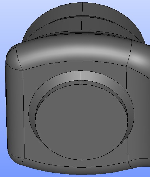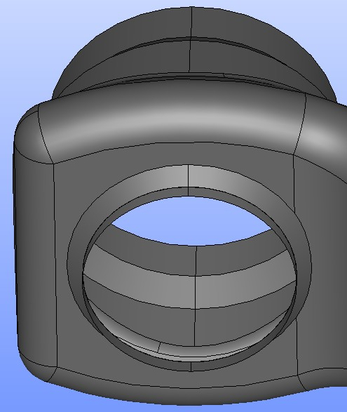


- There is a complex CAD model of the valve given at the beginning (see figure
 ), file name: Valvess.step.
 - This model shall be simplified, cleaned and converted into a STL format for the CFD simulation.
- It is reasonable to process and export just those model surfaces that come into contact with the flowing fluid – all the other surfaces are not necessary to deal with.
- Surface model for CFD analysis shall meet following conditions:
- The final surface model shall be clean. All the extra parts that takes no effect on fluid flow shall be removed.
- The final surface model must be fully closed – waterproof (see example and ).
- The final surface model shall have node to node ordering, sometimes also called vertex to vertex ordering (see example and ).
- The final surface model shall be split into several parts (boundaries) to allow the user to handle them individually (different boundary conditions, different evaluation of results, etc …). Generally speaking, it is reasonable to create rather many boundaries than just a few. CFD simulation can always take many boundaries. And still the user has more freedom in CFD set up and results evaluation. For example: inlet outlet wall-1 wall-2 side-A side-B movingWall-1 …
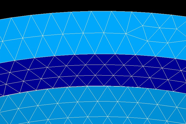
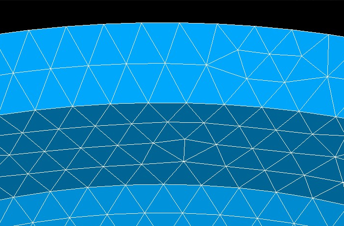
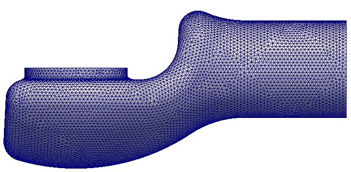
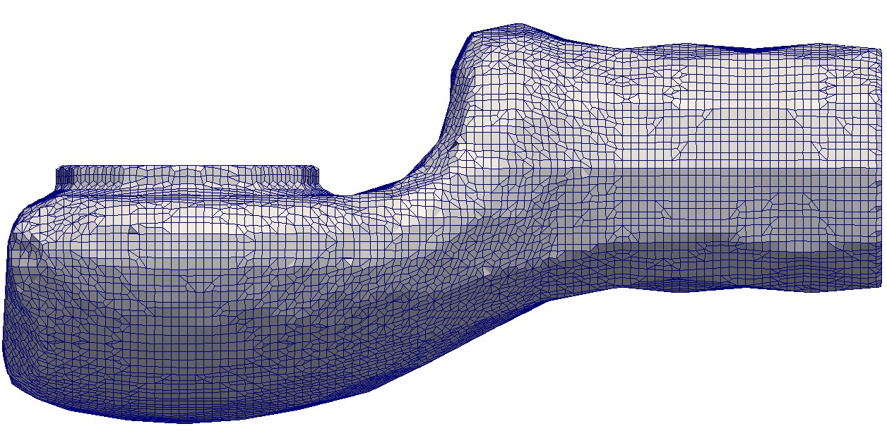
- The final surface mesh triangulation refinement shall be finer then the expected mesh which user would like to use in the CFD simulation. Otherwise it may happen the original shape of the triangulation would be visible in the resulting CFD mesh. By other words: The too much rough surface model can not be eliminated by CFD meshing any more. The difference between fine and coarse triangulation is shown in the figures and .