


This chapter mainly deals with requirements for input data and its fundamental properties which have to be satisfied to get outstanding results with TCFD workflow. Moreover, basic terminology for input mesh data and turbomachinery simulations are introduced.
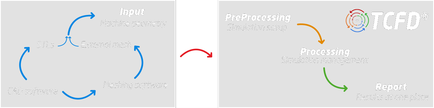
Figure above shows a simplified TCFDworkflow. It emphasizes that input geometry preparation is a separate process from TCFD. It has significant influence on results quality; wrong input generates wrong result. Make always sure that your input geometry, either STL files or external meshes, has the best possible quality. The main quality parameters and common errors will be presented later on in this Section.
Typically, the geometry is created or modified in some CAD software. Afterwards, TCFDusers have two basic options:
- Import the CAD geometry into some meshing program and generate the computation mesh. The resulting mesh (in *.msh format) can be directly imported into TCFD.
- Generate and export STL geometry from the CAD software and import the STL geometry into TCFD.