Each component has to be split into separate parts describing physical boundaries like inlet, outlet, walls, rotating walls, etc.
As a part of CFD process each part of the geometry has to be described with a special type of boundary conditions. Therefore, it is necessary to have an access to inlet and outlet boundaries for setting inlet and outlet boundary conditions and to physical walls to set wall boundary condition.
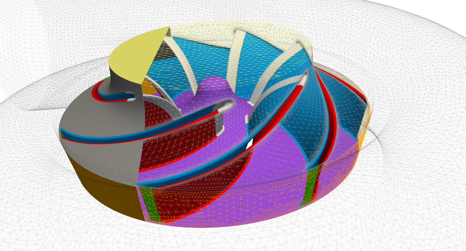
The physical walls should be split as well to distinguish which part is rotating and which part is fixed. Specifically, for a rotor component, one should split the boundary into hub, shroud and blade part which is useful for a specific turbomachinery evaluation. Additionally, blade can be split into leading edge, trailing edge, suction side and pressure side to define different refinement at these walls or for detailed pressure distribution evaluation and other postprocessing purposes.
An example of the splitting on a rotor component is visualized in Figure below.
INPUT RULE 4: Each component has to be split into physical boundaries.