


The usage of the filter is similar to other filters with one small difference: Because it allows (and requires) selection of different parts of the multi-part mesh, it is necessary to load all needed parts of the mesh, not just the internal mesh. The figure ![[*]](https://www.cfdsupport.com/wp-content/uploads/2022/02/crossref.png) demonstrates a typical selection of OpenFOAM case mesh and patches for the Turbo Unwrap filter.
demonstrates a typical selection of OpenFOAM case mesh and patches for the Turbo Unwrap filter.
demonstrates a typical selection of OpenFOAM case mesh and patches for the Turbo Unwrap filter. 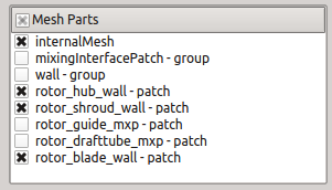
The filter will transform the cylinder-like mesh into a box. The meaning of its new dimensions is described in the table . In brief it can be said that the boundary  is the hub patch, the boundary
  is the shroud patch, the boundary
  is the one of inlet and outlet interfaces that is lower on the rotation axis and the boundary
  is the other one (higher on rotation axis). The boundaries on minimal and maximal
  coordinates are only artificial and were originally connected to each other.
The filter transforms only the cell data, not point data, so it may be necessary to apply the filter Cell data to point data afterwards to regain access to the point fields (which are necessary for usage of e.g. the Glyph filter).
coordinates are only artificial and were originally connected to each other.
The filter transforms only the cell data, not point data, so it may be necessary to apply the filter Cell data to point data afterwards to regain access to the point fields (which are necessary for usage of e.g. the Glyph filter).
. In brief it can be said that the boundary
The filter passes all cell data without change except for the vector fields U and URel, which are transformed into the new coordinate system  . Besides these two vector fields Turbo Unwrap also creates several additional vector fields, namely UStream and URelStream which should be used to construct streamlines in the transformed mesh and URelLIC, which should be used as an input for the Surface Line Integral Convolution (SurfaceLIC) integrator when displaying realtive velocity using SurfaceLIC representation.