Previous: Physical boundaries Up: Thinking in components Next: Watertight property
This is an automatically generated documentation by LaTeX2HTML utility. In case of any issue, please, contact us at info@cfdsupport.com.
Component interface alignment
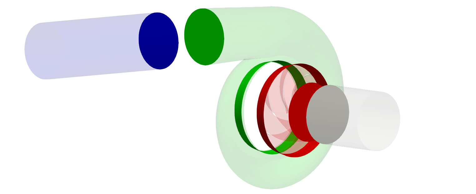
Each component has to be connected to at least one neighboring component. The corresponding interfaces, i.e., the inlet or outlet boundaries, have to be perfectly aligned to each other:
- the outlet boundary of the inlet pipe component has to be perfectly aligned with the inlet boundary of the rotor component.
- the outlet boundary of the rotor component has to be perfectly aligned with the inlet boundary of the volute component
- etc.
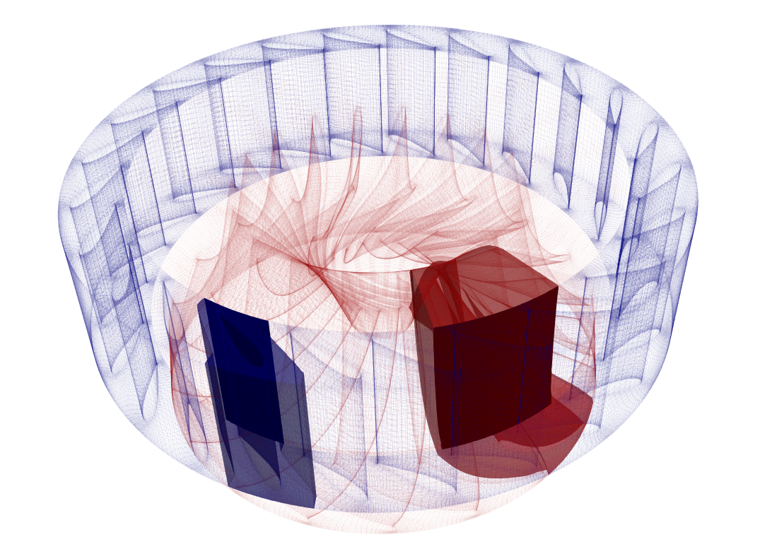
- In case of periodic segments: The corresponding interfaces of full wheel geometry (built from periodic segment interfaces) must be perfectly aligned.
See the Figures below:


INPUT RULE 5: Each component has to be perfectly aligned with its neighbor(s).
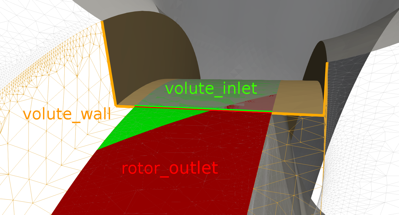
Another example of inlet-outlet interface alignment is depicted below. We can see the interface of the rotor and volute component. The rotor outlet (red) is perfectly aligned with the volute inlet (green). The orange color depicts a wall part of the volute component.

A usual mistake is to extended the green part to the whole orange cylindrical part. In this case the red part would be not perfectly aligned with the volute inlet which is not allowed.
TCFD![]() offers to impose so called mixing plane approach for components which defines just a segment of a full wheel geometry. In this case, neighboring interfaces have to be perfectly aligned in sense of its full wheel geometry, as depicted below.
offers to impose so called mixing plane approach for components which defines just a segment of a full wheel geometry. In this case, neighboring interfaces have to be perfectly aligned in sense of its full wheel geometry, as depicted below.

Previous: Physical boundaries Up: Thinking in components Next: Watertight property


