


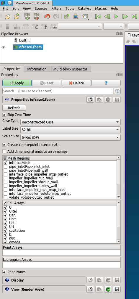
Step 1 — Load the OpenFOAM case into ParaView and make sure that you included the rotating zone. Depending on the way how you loaded the OpenFOAM case you can use either the “Include Zones” check-box above the mesh/field selection frames (figure ![[*]](https://www.cfdsupport.com/wp-content/uploads/2022/02/crossref.png) left), or “Read Zones” check-box below to read the rotating zone (figure right). The former way, more frequent in Linux, will add available zones at the end of the “Mesh Parts” selection list (and you need to select them manually). The latter way, more frequent in Windows, will automatically read all available zones after clicking on the “Apply” button. Choose some non-zero simulation time, select appropriate components (“Mesh parts”) and fields (“Volume fields”) and press “Apply”. This will load the mesh.
left), or “Read Zones” check-box below to read the rotating zone (figure right). The former way, more frequent in Linux, will add available zones at the end of the “Mesh Parts” selection list (and you need to select them manually). The latter way, more frequent in Windows, will automatically read all available zones after clicking on the “Apply” button. Choose some non-zero simulation time, select appropriate components (“Mesh parts”) and fields (“Volume fields”) and press “Apply”. This will load the mesh.
left), or “Read Zones” check-box below to read the rotating zone (figure right). The former way, more frequent in Linux, will add available zones at the end of the “Mesh Parts” selection list (and you need to select them manually). The latter way, more frequent in Windows, will automatically read all available zones after clicking on the “Apply” button. Choose some non-zero simulation time, select appropriate components (“Mesh parts”) and fields (“Volume fields”) and press “Apply”. This will load the mesh. 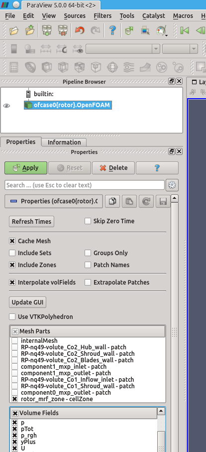
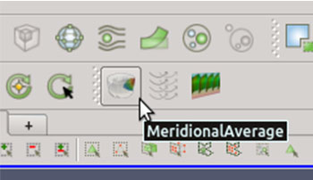
Step 2 — Meridional average can be calculated by an application of the filter Meridional Average, which is part of Turbo Blade Post. You should see the icon of the filter in the toolbar. Note that the filter is available (i.e. coloured and clickable) only when the data selected in “Pipeline browser” are of the type “Unstructured grid” (see panel “Information”, section “Statistics”). If we loaded several blocks (mesh parts), we would first need to extract the appropriate mesh zone using the filter Extract block, see figure .
. 
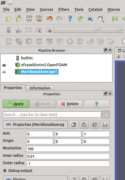
Step 3 — The properties of the filter Meridional Average are shown in the figure . Some of the options are advanced and can be displayed using the “Toggle advanced properties” button (wheel symbol). The setup consists of a just a few numbers: (a) rotation axis, (b) axis origin, (c) clip out radius and (d) resolution. The “resolution” is the number of points of the resulting projection in radial or axial direction, whichever is larger. A non-zero “Inner radius” is necessary if the rotation axis pierces through the computational mesh, i.e. if there is no hole along the axis. In this tutorial the rotation axis is the axis  , the origin coincides with the coordinate system origin and we choose the clip out radius to be 0.01 m, as shown in the figure. Confirm the settings by pressing the “Apply” button. A non-zero “Outer radius” can be used to clip out some unwanted parts.
. Some of the options are advanced and can be displayed using the “Toggle advanced properties” button (wheel symbol). The setup consists of a just a few numbers: (a) rotation axis, (b) axis origin, (c) clip out radius and (d) resolution. The “resolution” is the number of points of the resulting projection in radial or axial direction, whichever is larger. A non-zero “Inner radius” is necessary if the rotation axis pierces through the computational mesh, i.e. if there is no hole along the axis. In this tutorial the rotation axis is the axis 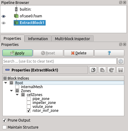
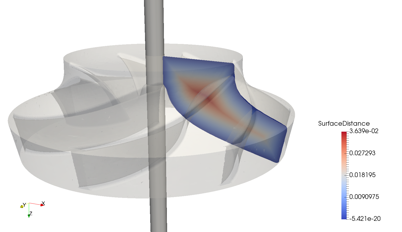
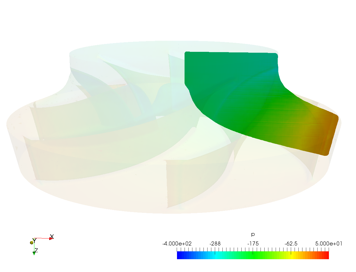
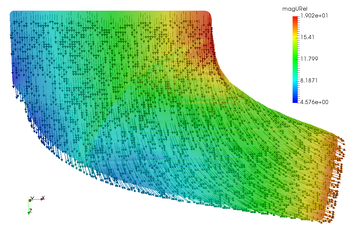
Step 4 — Once the filter completes, it will produce a projection as in the figure . By default, it shows the distance of individual points to the nearest surface (hub, shroud, inlet or outlet). However, all scalar fields have been averaged by the filter and are available in the field selection drop-down list in the main toolbar. The figures and show the averaged results for static pressure and relative velocity, respectively.
. By default, it shows the distance of individual points to the nearest surface (hub, shroud, inlet or outlet). However, all scalar fields have been averaged by the filter and are available in the field selection drop-down list in the main toolbar. The figures and show the averaged results for static pressure and relative velocity, respectively.