


![[*]](https://www.cfdsupport.com/wp-content/uploads/2022/02/crossref.png) .
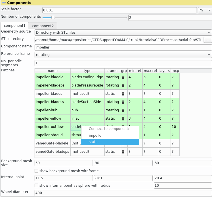
The computational domain can be split into any number of sub-domains – the components. Components are meshed individually, they can be individually set as rotating and individually postprocessed.
Each domain can have any number of inlets and outlets and can be connected to any number of other components through inlet or outlet interfaces. There can be just one inlet interface from component A to component B, as well as just one outlet component. As the names “inlet” and “outlet” interface suggest, they should be used with consideration of the anticipated direction of flow. This pre-orientation is a requirement between rotating and non-rotating components, where the Mixing plane will be used. Between co-rotating components it is not necessary, as the cyclicAMI interface used in those cases is symmetrical.
At any time, the current topology of the components is graphically represented in the component graph at the end of “Components” section. A sample auto-generated component graph is displayed in Figure .
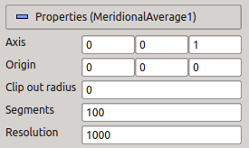
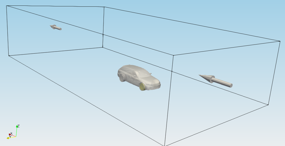
If one of the simulation types stator, virtualTunnel, propeller or windTurbine is chosen, checkbox “Bounding box” appears in the ”Components” section. Using this feature, TCFD can be used for simulations of external flows. If “Bounding box” is checked, axis oriented box is added, which works as a virtual wind tunnel, and another three entries will show up (Figure ):
). After the bounding box is added, its patches will appear in the “Patches table”.
.
The computational domain can be split into any number of sub-domains – the components. Components are meshed individually, they can be individually set as rotating and individually postprocessed.
Each domain can have any number of inlets and outlets and can be connected to any number of other components through inlet or outlet interfaces. There can be just one inlet interface from component A to component B, as well as just one outlet component. As the names “inlet” and “outlet” interface suggest, they should be used with consideration of the anticipated direction of flow. This pre-orientation is a requirement between rotating and non-rotating components, where the Mixing plane will be used. Between co-rotating components it is not necessary, as the cyclicAMI interface used in those cases is symmetrical.
At any time, the current topology of the components is graphically represented in the component graph at the end of “Components” section. A sample auto-generated component graph is displayed in Figure .
If one of the simulation types stator, virtualTunnel, propeller or windTurbine is chosen, checkbox “Bounding box” appears in the ”Components” section. Using this feature, TCFD can be used for simulations of external flows. If “Bounding box” is checked, axis oriented box is added, which works as a virtual wind tunnel, and another three entries will show up (Figure ):
). After the bounding box is added, its patches will appear in the “Patches table”. 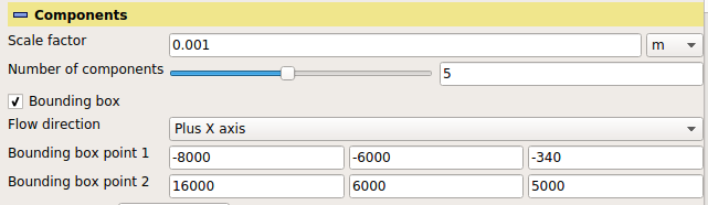
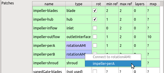
Patches table gives summary of all patches for each component, where each row of this table represents one patch and its properties.
First column is the name of the patch, which is non-editable.
Second column is the patch type, which is one of the following:
. This change will be indicated by a colour change of the rows.Besides the specific type, every patch can be either rotating or non-rotating, which is controlled by the column labeled “frame”:
Further columns contain the minimal and maximal refinement and number of layers, which are used during the meshing. It is possible to change the value by double-clicking on the required field and either modifying the value by hand or using the spin-box buttons. The lock symbol in the “grp” column has two modes:
Finally, the column “mxp”, available only for inlet and outlet interface patches, contains the number of Mixing planes . If “0” is given, the components will be connected using cyclicAMI (direct weighted interpolation); higher values specify number of Mixing plane strips (circular averaging) to use. Some columns may not be present for specific geometry sources (e.g. for an external OpenFOAM mesh).
Further options in this section are
, and enables the following three parameters.If a cylindrical background mesh is selected, then the interpretation of “Background mesh size” changes. Instead of cell sizes in the ![]() ,
, ![]() and
and ![]() axes it sets the approximate cell sizes in radial, circumferential and axial directions (with respect to the chosen axis).
axes it sets the approximate cell sizes in radial, circumferential and axial directions (with respect to the chosen axis).
Further advanced options in this section are:
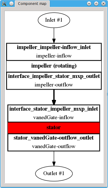

 ) displays all components and their interfaces. Thick arrows point always from inlet to outlet interface. If some interface is not available (or connected), the arrows become dashed and point elsewhere. This then indicates an invalid topology. All components must be connected into a single domain using the inletInterface/outletInterface pairs. The graph can be detached from the Properties panel by a double-click; this transfers it to a new window. The separated window stays by default on top of all other windows (this can be manually unselected in the window manager menu). Further double-click merges the window back into the panel, as does also closing the window in any other way. The colours in the graph correspond to colours of the individual components in RenderView, assuming the colouring by vtkBlockColors is chosen. The graph also displays all inlets and outlets, with inlet and outlet components assigned to them. In a valid setup, all inlets and outlets should have exactly one inlet boundary condition and outlet boundary condition, respectively, assigned to them. If some inlet/outlet lacks inlet/outlet boundary condition, its name becomes red. If some inlet/outlet has more than one inlet/outlet boundary condition, its name becomes red, and so do the inlet/outlet boundary condition arrows pointing to it.