At the interface between stator and rotor part, for each variable one can prescribe either Frozen Rotor boundary condition or Mixing Plane boundary condition. Frozen Rotor maps variable directly to the neighbour patch. Mixing Plane computes the variable average first and then maps just the average value to the neighbour patch. Both approaches can be combined (each variable can have its own option). Both approaches have benefits and drawbacks to each other. Authors of this methodology recommend to prefer Mixing Plane boundary condition.
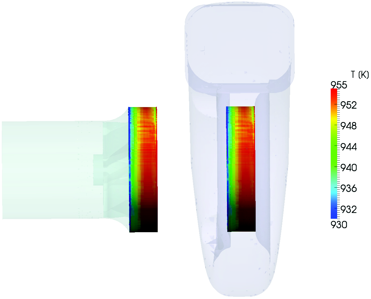
Figure: Radial turbine. Example of Mixing Plane Averaging from stator region to rotor region.
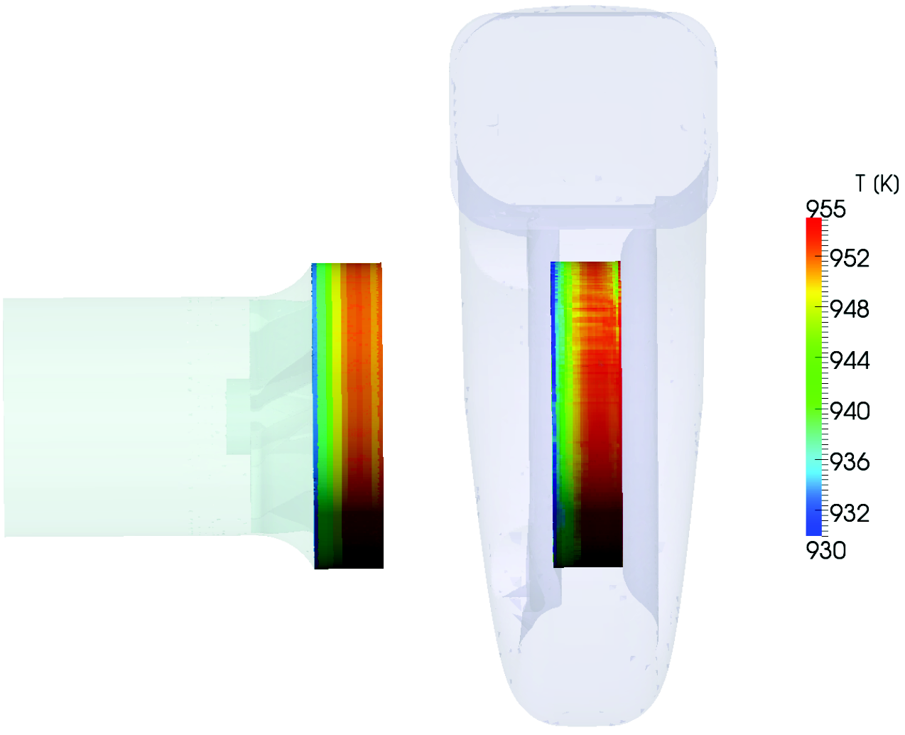
Figure: Radial turbine. Example of Frozen rotor interpolation from stator region to rotor region.