


Step 1 — Load the rotor part of an OpenFOAM case into ParaView using the command paraFoam -region rotor. Avoid loading the whole mesh; choose only the blade walls and the hub and shroud patches. Choose some non-zero simulation time, select appropriate components (“Mesh parts”) and fields (“Volume fields”) and press “Apply”. This will load the necessary patches, figure ![[*]](https://www.cfdsupport.com/wp-content/uploads/2022/02/crossref.png) .
.
. 
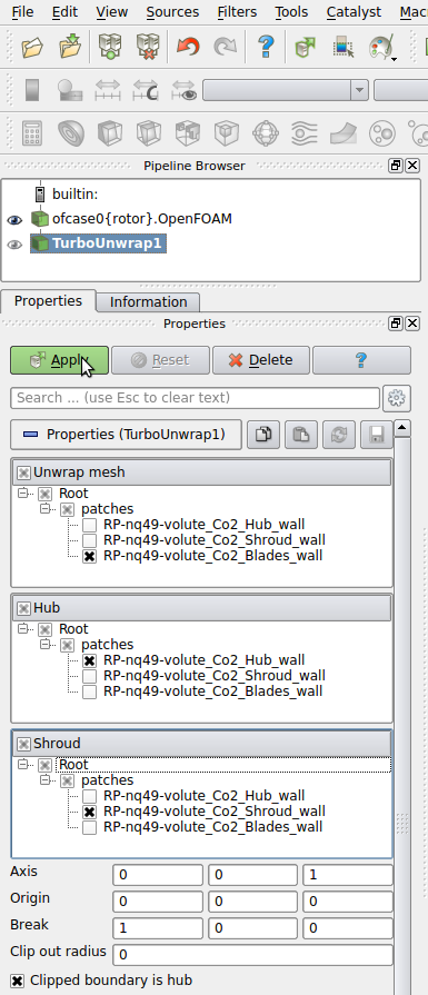
Step 3 — The basic properties of the filter Turbo Unwrap are shown in the figure . When the advanced options are hidden, there are only a few options to define. First of all, it is necessary to choose the blade wall patch, that will be transformed, and the hub and shroud patches, which will serve as a leaders to define the transformation. After the transformation is done, hub and shroud will be perfectly flat and parallel to each other, conformly deforming the mesh in between. If multiple mesh parts are selected in the “Unwrap mesh” window or multiple patches are selected in “Hub” or “Shroud” windows then they will be internally merged into a single entity before proceeding. In this example the mesh is well prepared and we can just select the three items that we loaded in the first step.
. When the advanced options are hidden, there are only a few options to define. First of all, it is necessary to choose the blade wall patch, that will be transformed, and the hub and shroud patches, which will serve as a leaders to define the transformation. After the transformation is done, hub and shroud will be perfectly flat and parallel to each other, conformly deforming the mesh in between. If multiple mesh parts are selected in the “Unwrap mesh” window or multiple patches are selected in “Hub” or “Shroud” windows then they will be internally merged into a single entity before proceeding. In this example the mesh is well prepared and we can just select the three items that we loaded in the first step.
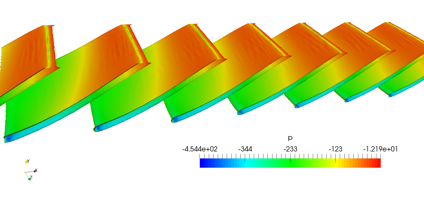
Step 6 — Click on “Apply”. The transformation should be relatively fast, because the sufrace mesh of the blades is orders of magnitude easier to process than the full volume mesh. It may be necessary to zoom in or out a little (depending on the geometry) to make the result fit to window. Outcome of this step is shown in the figure , where the blades are coloured by pressure.
, where the blades are coloured by pressure.
Step 7 — Having the blades transformed we can now cut them at a specific height ( -axis) using the filter Slice. This will result in several two-dimensional intersection contours.
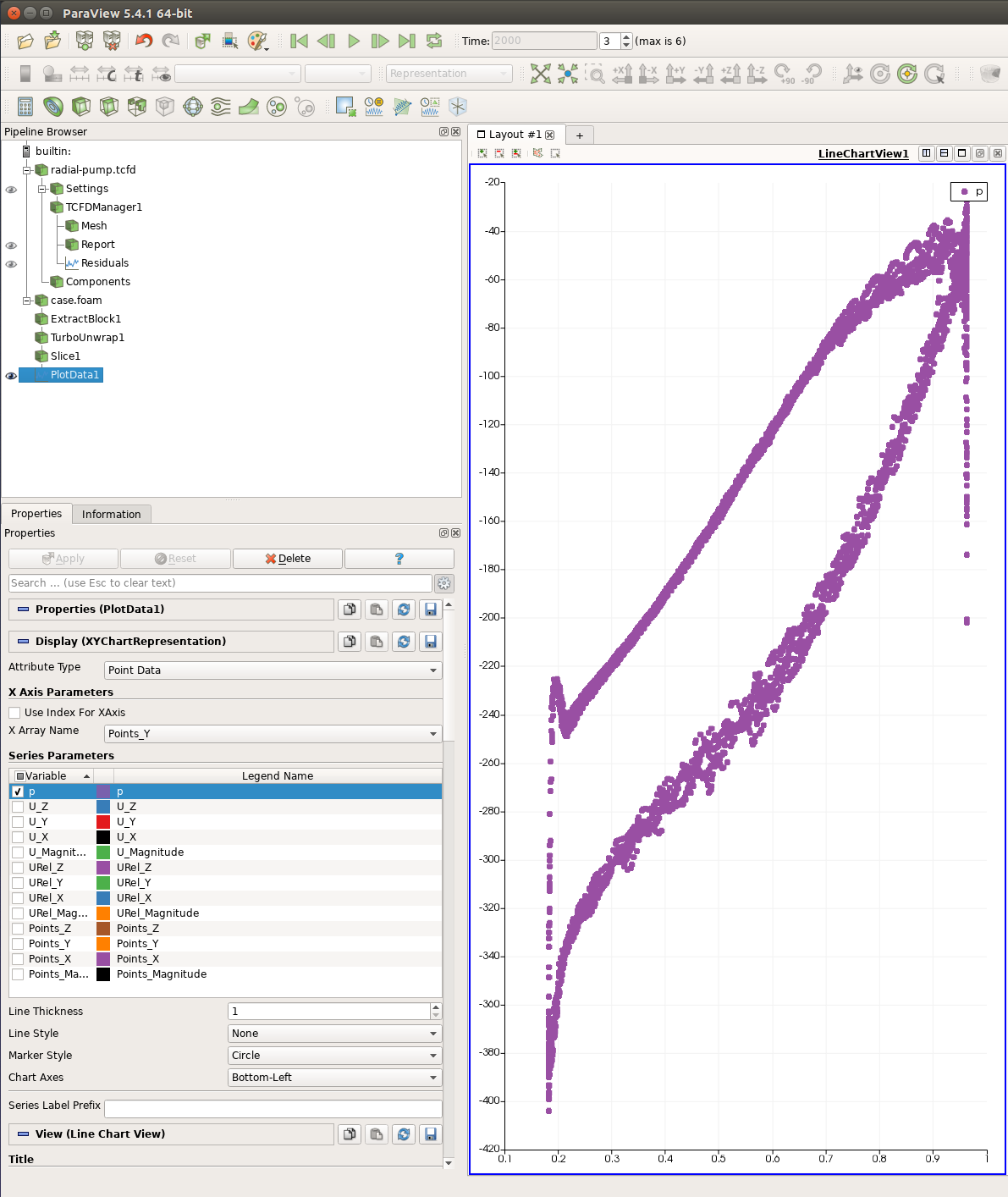
Step 8 — Add the filter Plot Data from Filters > Alphabetical or using Filters > Search. Unselect all fields but pressure (see figure ). Above the field selection box use “Points_Y” as the “X Array Name”. This will use points’ Y coordinates as the data for the horizontal axis. Below the field selection box use “None” as “Line Style” and “Circle” as “Marker Style”. This will only show one bullet per a mesh point, making the result independent on the order of the projected points. Now press “Apply”. You should obtain a similar figure to .
). Above the field selection box use “Points_Y” as the “X Array Name”. This will use points’ Y coordinates as the data for the horizontal axis. Below the field selection box use “None” as “Line Style” and “Circle” as “Marker Style”. This will only show one bullet per a mesh point, making the result independent on the order of the projected points. Now press “Apply”. You should obtain a similar figure to .