


- In this section the valve body will be split into two parts.
- These two following names will be used: “inlet part” and “outlet part“
- The splitting plane will be the cap of the valve plug in a fully closed position.
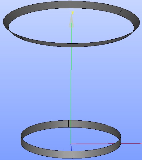
- Start with showing the newly generated shell of the valve plug (see figure
 ).
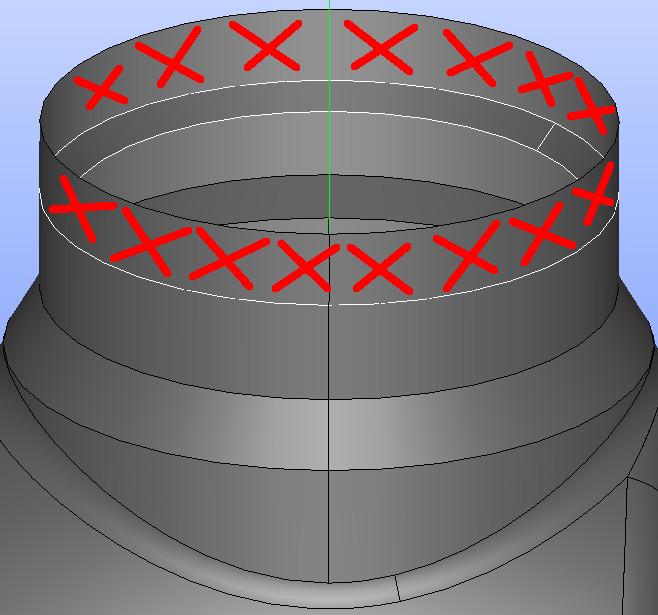
). - Take a look at the overlapping faces of the valve plug and the valve body: region12-first-version and region3-closed
- These two parts are shown in the figure .
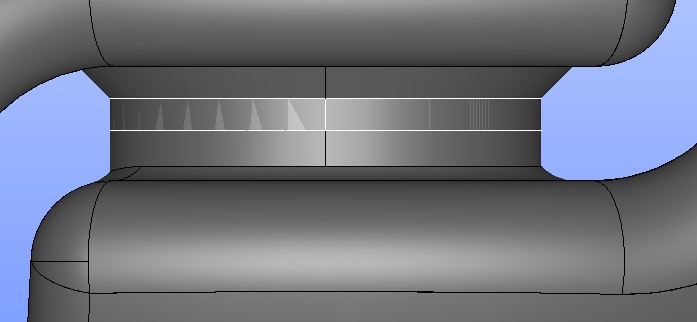
- The details of overlaying parts of the valve body compound and the valve plug shell are in the figures and . Exploded faces of compound will be cut on these places.
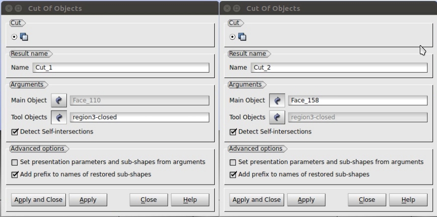
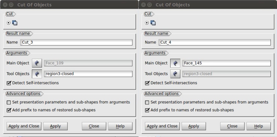
- Now cut off the overlapping faces of the valve body using the valve plug as a cutting tool.
- Make 4 cuts in total. In the upper menu Operations > Boolean > Cut – the window “Cut of Objects” appears – follow figures (top cut) and (bottom cut).
- Main Object consists of faces of the valve body and Tool Object consists of faces of the valve plug.
- Then click Apply or Apply and Close.
- Do this four times, follow the figures: ,
- Now explode (split) the first two cuts into the faces.
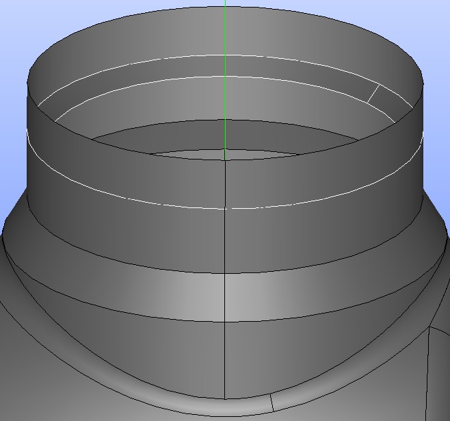
- Hide or remove the faces of the compound cut higher than the edge of the plug (see figure ).
- At the bottom there will be created an interface between two regions – “inlet part and outlet part of the valve body (see figure ).